Figure 5 control panel, Figure 5: control panel – Envirco BSC User Manual
Page 28
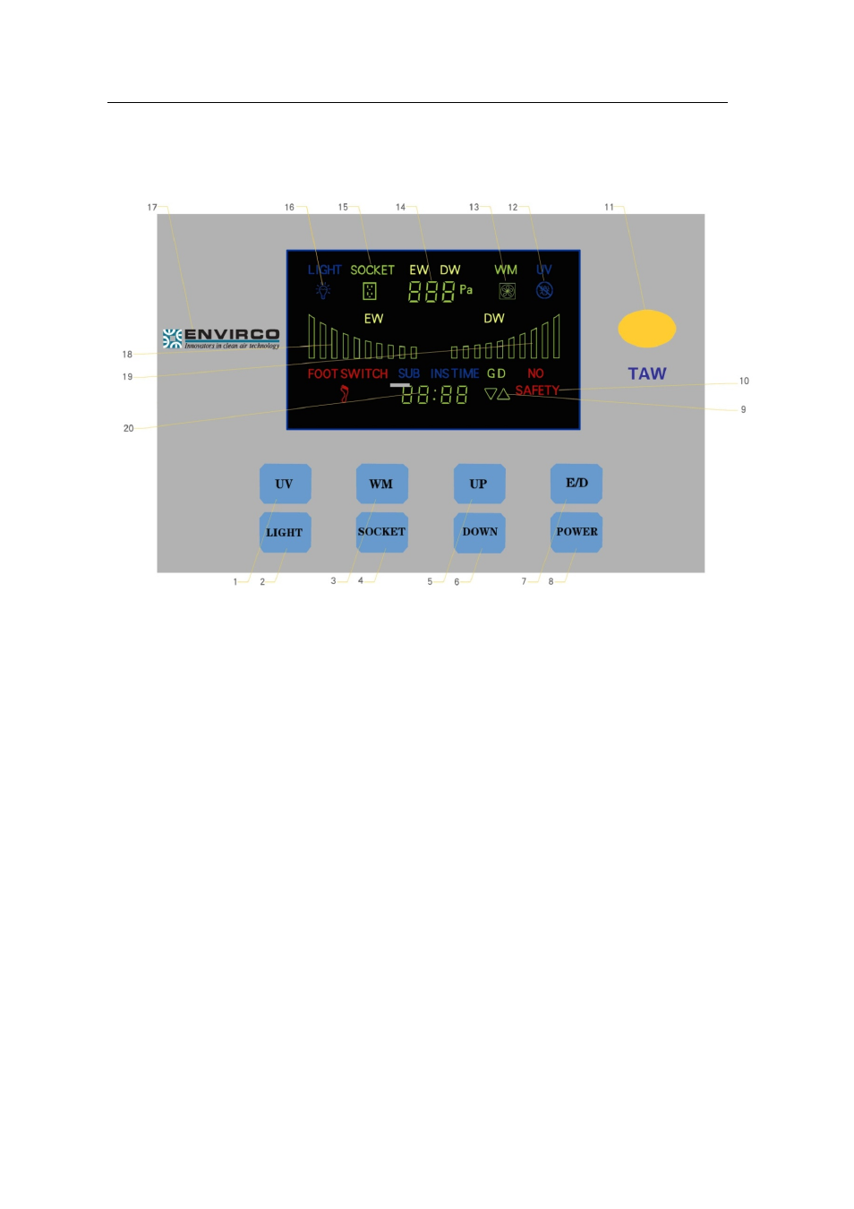
FIGURE 5: CONTROL PANEL
1 . Uv–light
28
2 . Light
3 . Wm
(fan)
4 . Socket
5 . Up (control for glass door)
6 . Down (control for glass door)
7. E/d (intake and exhaust air changing)
8. Power
9. Display(glass door)
10. Display (security stcabinet)
11. Display (security stcabinet)
12. Remote control receiver
13. UV work state display
14. Blower display
15. Intake or exhaust air display
16. Socket display
1 7 . Lightdisplay
18. Logo
(envirco)
19. Dynamic exhaust air display
20. Dynamic intake air display
21. Time reserve display