Operating instructions – EDCO CPU-12 User Manual
Page 5
E-CPU12-I-0113
Printed in USA
TVW
©2013
Page 5
100 Thomas Johnson Drive, Frederick, MD 21702-4600 USA
Phone (301) 663-1600 • 1-800-638-3326
Fax (301) 663-1607 • 1-800-447-3326
Website: www.edcoinc.com
Email: [email protected]
Before Starting the Engine:
•
Inspect machine before each use according to the Maintenance Schedule on page 11.
•
Locate and be familiar with all engine and operating controls (Figure 2).
•
Inspect cutters carefully before installing. Use the correct drum assembly confi guration for the job. Make sure
drum
assemblies are correctly mounted.
•
Adjust the extendable handles for operator comfort and safe operation. Be sure to retighten handle locks once
handles are
positioned. (Figure 2, Item #10)
•
Be sure cutter head is raised to the full “up” position using the drum lift lever on the console. (Figure 2, Item #7)
This EDCO Scarifi er
uses a battery powered hydraulic pump.
•
Lift up on the cam lift lever to lower the rear wheel, this action raises the drive wheels. Manuver the machine into
position over the work area.
•
Lower the cam lift lever to raise the third wheel, engaging the drive wheels.
Never lower cutter head with rear wheel raised or raise the rear wheel while the cutter head is low-
ered. Death or serious personal injury and/or damage to the equipment can result.
For Gasoline Models: Units are shipped new from the factory without gasoline or oil, it will need to be added before
it is used. Check the Engine Manufacturer’s Owner’s Manual for instructions on break-in, servicing and use of engine.
For Electric Models: Be sure the “off” button is depressed before hooking up power source. If the cord does not
mate with the connector provided, consult a qualifi ed licensed electrician before continuing. Do not alter the plug or
force it to fi t. Verify that the equipment is properly grounded.
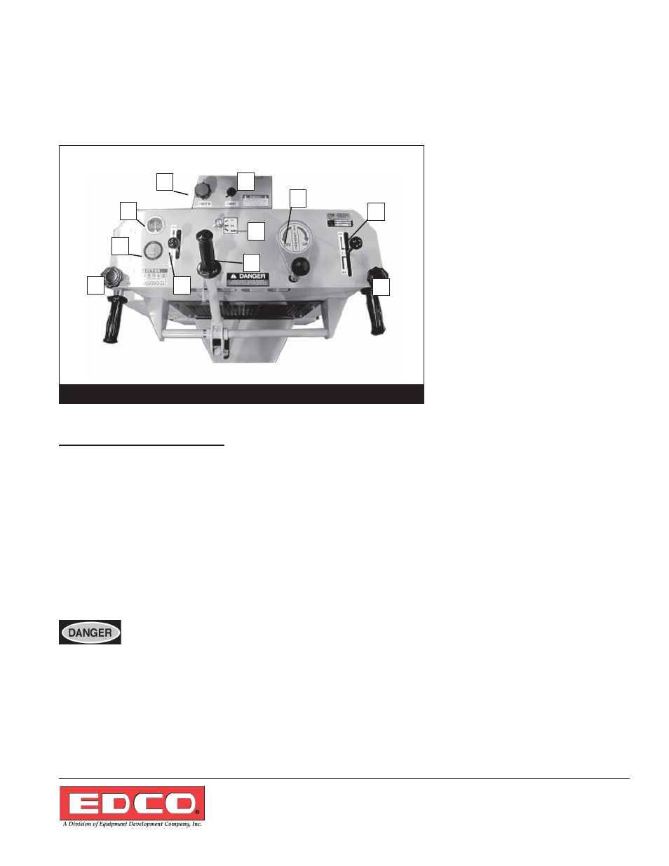
Operating Instructions
1. Ammeter
2. Throttle
3. Choke
4. Depth Control Knob
5. Drive Control Lever
6. Hour
Meter
7. Hydraulic Drum Lift Lever
8. Cam Lift Lever
9. Ignition
Switch
10. Handle Lock
Figure 2
1
2
10
10
7
8
9
3
4
5
6