Step 9 — install all accessories, In. diameter and, Fig. 24 — typical economi$er sensor wiring – Carrier 50TJ016-028 User Manual
Page 15
15
VENTILATION AIR (Minimum Position Set Up) — If ven-
tilation air is not required, skip this section. If ventilation air is
required, perform the following:
1. The indoor fan must be on to set the ventilation air.
Either put the thermostat in the continuous fan mode or
jumper the R and G terminals at the rooftop unit con-
nection board.
2. Locate the minimum position (MIN POS) potentiometer.
Turn the potentiometer full CCW to fully close the out-
door air dampers. Turn the potentiometer gradually
clockwise (CW) to the desired position. See Fig. 16.
3. Replace the filter access panel. See Fig. 18. Ensure the fil-
ter access panel is securely engaged.
4. Calculate the minimum airflow across the EconoMi$er.
a.
Calculate % of outside air using the following
formula.
% Outdoor air through EconoMi$er
b. Multiply total CFM by percentage outdoor air, this
gives outdoor air volume in CFM.
Step 9 — Install All Accessories —
After all the
factory-installed options have been adjusted, install all field-
installed accessories. Refer to the accessory installation instruc-
tions included with each accessory.
MOTORMASTER® I CONTROL INSTALLATION
(50TJ016 and 020 Only)
Install Field-Fabricated Wind Baffles — Wind baffles must
be field-fabricated for all units to ensure proper cooling cycle
operation at low ambient temperatures. See Fig. 25 for baffle
details. Use 20-gage, galvanized sheet metal, or similar
corrosion-resistant metal for baffles. Use field-supplied screws
to attach baffles to unit. Screws should be
1
/
4
-in. diameter and
5
/
8
-in. long. Drill required screw holes for mounting baffles.
% Outdoor air =
Mixture Temp – Return Air Temp
Outdoor Temp – Return Air Temp
Personal Injury Hazard. Avoid possible injury by keep-
ing fingers away from damper blades.
To avoid damage to the refrigerant coils and electrical com-
ponents, use recommended screw sizes only. Use care
when drilling holes.
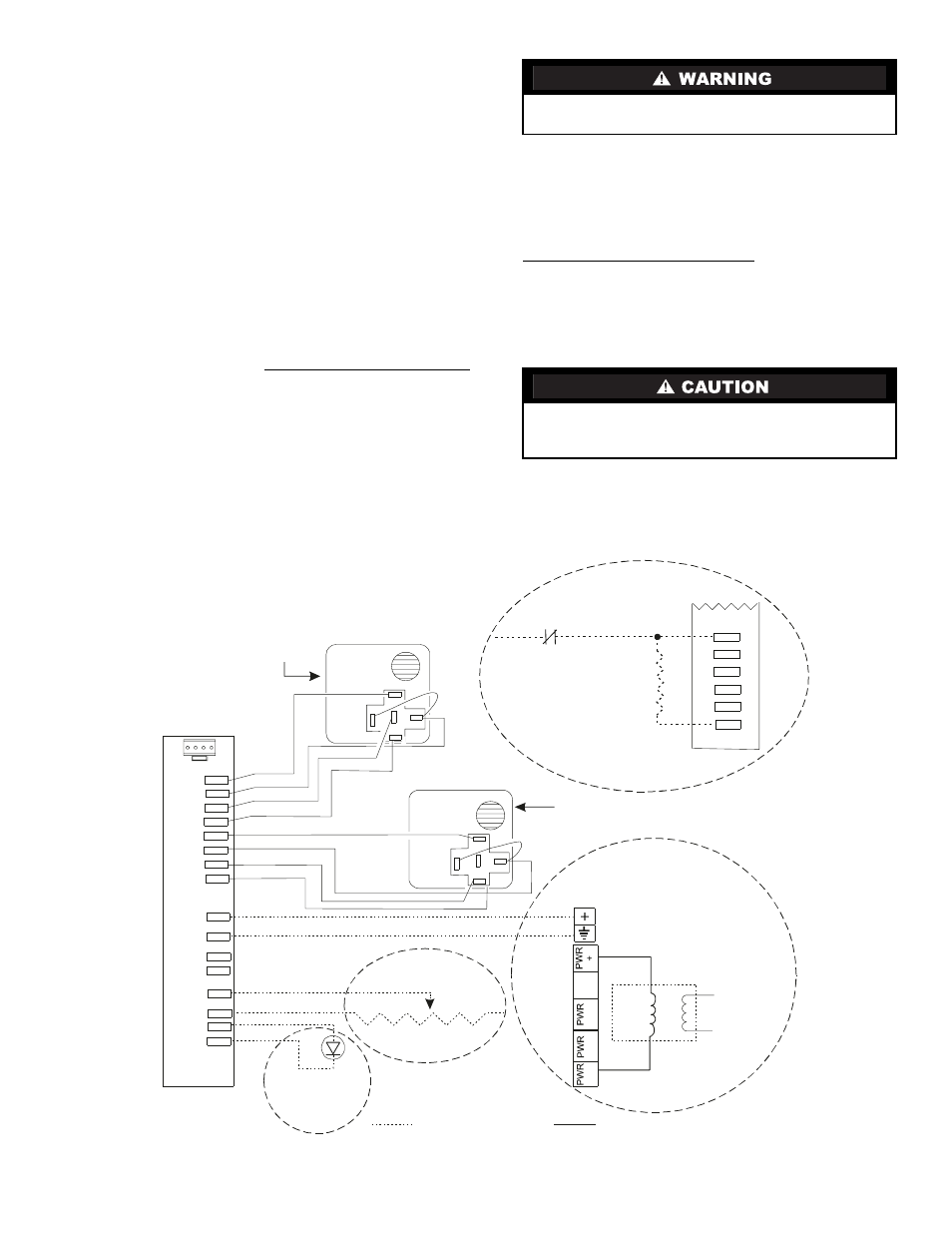
20 mA LED
1k ohm Potentiometer
2 to 10 VDC at
0 to 2000 ppm
CO2 Sensors:
Rem ote
M inim um Position
Rem ote
LED
Outdoor Air Enthalpy
CROUTENT001A00
Return Air Enthalpy
CRRETENT001A00
Line
Voltage
CO
CO
COM
DAT
COM
REM
POT
COM
LED
COM
2
2
OAT
COM
OAH
+15V
RAT
COM
RAH
+15V
C
O
M PW
O
U
T T
T
Violet
C
O
M PW
O
U
T T
T
Violet
Field-supplied W iring
W iring Included
470 ohm
5 watt
Resistor
24 VAC m ust be present
on BI for the system to be
unoccupied.
Unoccupied Control
(Part num ber on the control
m ust be AD-DM E1701-1
or AD-DM E1711-1.)
Unoccupied
Contact
Tan
Violet
W hite
Red
Tan
Violet
W hite
Red
24 V
A
C
20 V
A
NOT
USED
1
2
-
(+)
3
2
3ZCSENCO
Fig. 24 — Typical EconoMi$er Sensor Wiring