Char-Broil 463247412 User Manual
Page 19
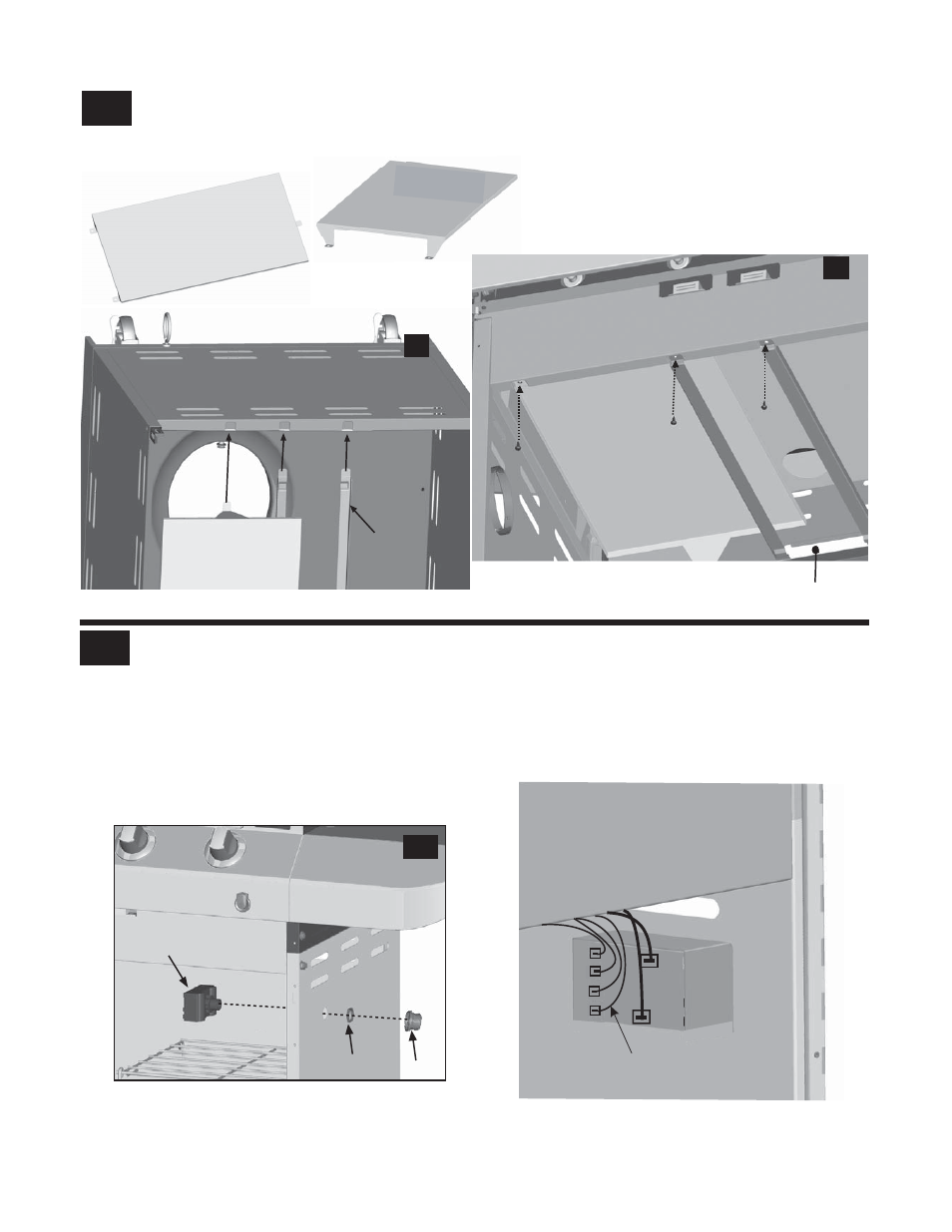
13
19
*This side UP
Tank heat shield
12
Inside of cart, insert rear shield tab into left slot on upper of lower back panel.
Attach front shield tabs under front brace and attach right and
Insert left and right grease tray rails into slots
left rails under front brace with three #8x3/8” self-tapping screws, shown B.
Rear
Front
Tank heat shield
Tank heat shield
Cart lower back panel
Right rail
Left rail
Front Brace
Right rail
Left rail
#8x3/8”
self-tapping screw
Grease tray opening
beneath grease tray opening in upper back panel, shown A.
for clarity of illustration
Note: some parts omitted
A
B
Connect each of the wires from the main burner electrodes, and sideburner electrode into the back of the Electronic Ignition
Module.
T
otal (4) connections.
Connect the two wires(A and B) from the switch wiring harness into the back of the Electronic Ignition Module.
NOTE: Switch terminals are larger than electrode terminals and should only be installed in location shown as A,B.
Wire
1
4
3
2
A
B
Total (2) connections.
Release the cap and nut from electronic ignition module. Attach electronic ignition module to the cart right side panel with
the nut and cap, shown A.
ignition module
Electronic
Right side panel
A
Cap
Nut