Drawmer, Installation audio connections – Drawmer DS101 500 Series Noise Gate User Manual
Page 4
4
DRAWMER
INSTALLATION
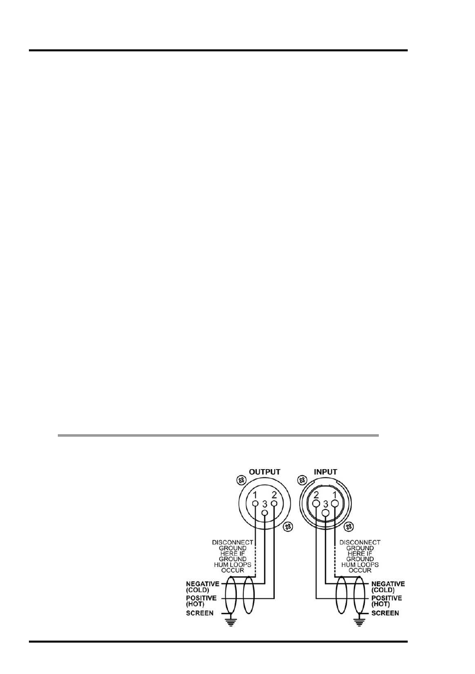
AUDIO CONNECTIONS
The inputs and outputs found on
the back of the 500 rack are
e l e c t r o n i c a l l y b a l a n c e d o n
conventionally wired XLRs (pin
1 screen, pin 2 hot, pin 3 cold
and XLR shell is connected to
chassis).
The use of balanced wiring is
recommended.
(Please consult your 500 series
manual for further information).
Congratulations on purchasing your new Drawmer product. In order to protect your
new investment, please take a few moments to fill out the warranty registration
card provided in the box, or alternatively visit our website at www.drawmer.com and
fill out the form online.
Quick and easy to do, registering your audio product is important and helps to
serve as proof of ownership for any future warranty issues.
The DS101 does not function stand alone and requires the power supply and the
audio connectors provided by an API 500 series compatible rack frame (not
included).
Installing the DS101 into a 500 Series compatible rack.
1.
Before you install anything be sure to turn off the 500 series rack and unplug it
from the mains supply. The 500 Series have not been designed for ‘hot swapping’
and doing so could damage this and other products within the unit, making any
warranty void.
2.
After removing the DS101 from its packaging locate a single free slot per DS101.
Note that if you are installing more than one DS101 locate them in slots adjacent to
each other so that the linking feature can work.
3.
Whilst looking down into the 500 series rack ensure that the DS101 card edge
connectors line up with the EDAC type connector of the rack, then gently push the
DS101 in place keeping it as square as possible until it is fully located. Do not use
excessive force!
4.
Tighten the two front panel screws.
5.
Connect the XLR cables to the rear and power up the rack. The DS101 will power
automatically and should be ready to use.