D.A.S. Audio DR Active Series User Manual
Page 11
Manual del Usuario
User’s Manual
/ DR active /
5
J
J
A
B
C
D
E
F
G
H
I
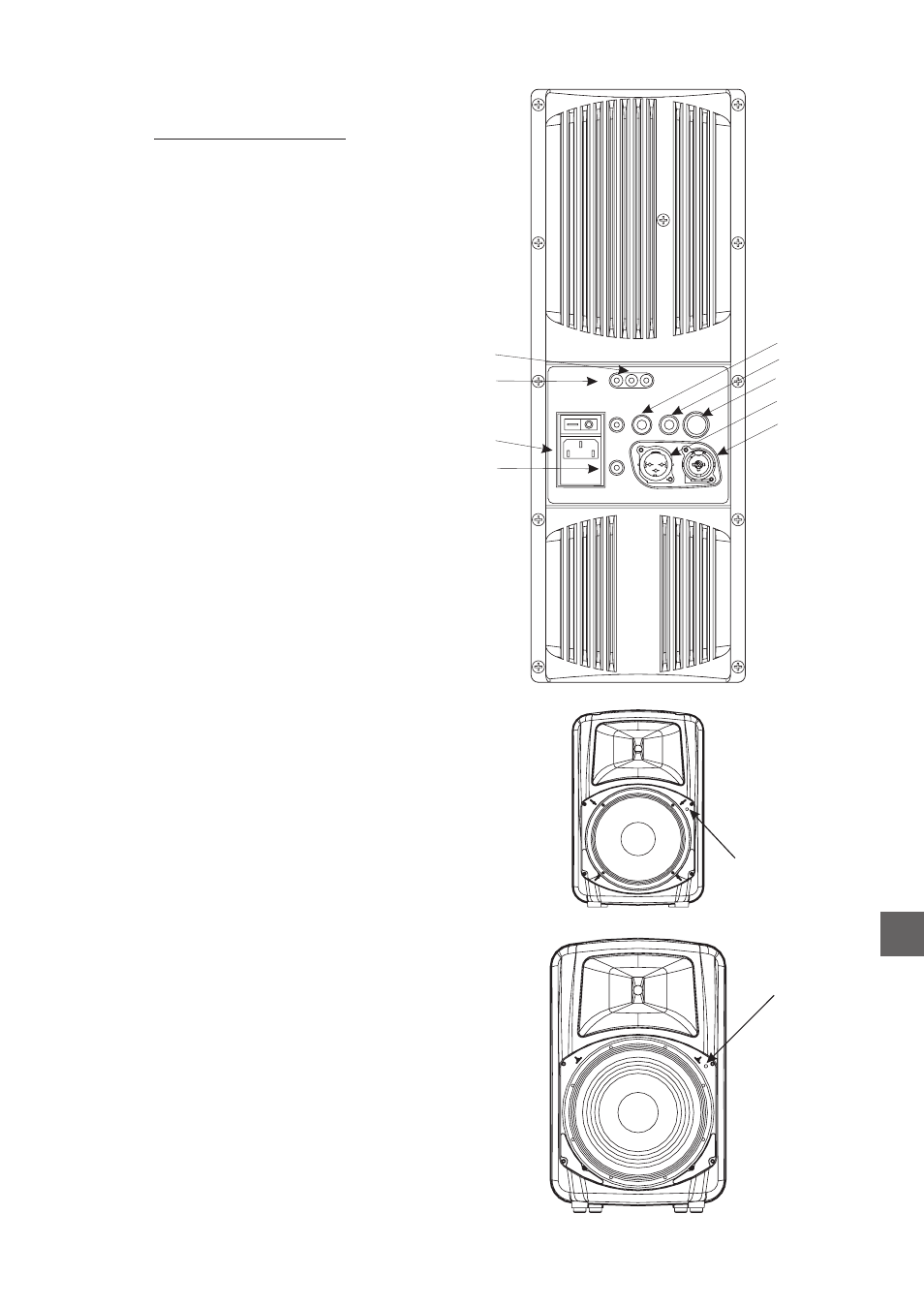
DR-112A
DR-115A
and
amplifier
A) MIC/LINE :
Switches
between
microphone
and
line
modes. The indicator light on the left hand side of
the switch is lit when the microphone mode is
activated.
B) LOW CUT:
D) LOOP THRU :
Used for paralleling several units, which will
share the same input.
E) LINE INPUT :
Balanced signal XLR. Pin assignments as
follows :
1 = GND (Ground).
2 = (+) Non-inverted signal.
3 = (-) Inverted signal.
AC INPUT :
Switches a 100 Hz high-pass filter on and off.
C) LEVEL:
Controls the level of the system.
This balanced connector
has three pins for which pin assignments are as
follows :
1 = GND (Ground).
2 = (+) non-inverted signal.
3 = (-) inverted signal.
F) ON :
Power-on indicator green led.
G) SIGNAL :
Signal presence indicator green led.
H) LIMIT :
Limiter indicator leds for each of the frequency
bands, LF and HF.
I)
Standard IEC male connector, fuse holder and
power switch. Plug the unit mains cable here.
Replace fuse on the fuse holder with a same type
fuse, if the fuse is blown.
Power switch (with standard symbols):
Turns the unit on = ’|’
Turns the unit off = ‘O’
J) Power-on indicator red led (at the front of
the box).
EN