Comtrol RM i PCI V.90 User Manual
Page 2
Installing the RocketModem
To install a single RocketModem, follow these steps:
Note: For best results we recommend installing
RocketModem cards one at a time, to simplify the
configuration process.
1.
Turn your computer off and remove the system unit
cover.
2.
Select an available PCI slot and remove the slot
cover.
3.
Write down the serial number of the RocketModem.
4.
Insert the RocketModem in the expansion slot.
Make sure it is seated securely.
5.
Reinstall the expansion slot cover screw.
Note: When powered up, the RocketModem
generates significant heat. After you install
and configure the RocketModem, make sure
the system cover is closed and the ventilation
fan is unobstructed. If you install more than
one RocketModem, you may want to add an
additional internal cooling fan.
6.
Connect standard RJ11 (telephone) cables between
the RocketModem ports and the phone line jacks.
7.
Power up the computer and run the Diagnostics
program to verify that the RocketModem is installed
and working correctly. For instructions, see the
Using the Diagnostics discussion in this card.
8.
After the RocketModem has successfully passed
diagnostics, install and configure the device driver
for your operating system, using the RocketModem
Software Installation and Configuration Guide or
the
README
file released with the driver.
After you have successfully installed one RocketModem,
you can install additional RocketModem cards by
repeating this process.
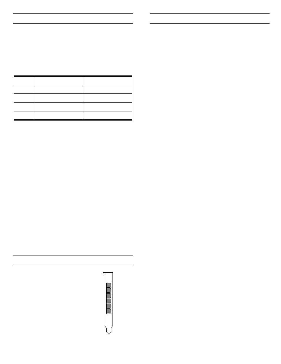
Port Identification
The modem ports on the RocketModem
mounting bracket are numbered as
shown in the illustration at right. The
port on the “top” edge of the card is
modem Line 1, and the port at the
“bottom” edge of the card, nearest the
bus connector, is Line 6.
A four-modem version of the
RocketModem card is also available. The
four-modem version uses the same
mounting bracket and connector block
as the six-modem version, but Jacks 5
through 6 are blocked with blank plugs.
The four-modem model is not user-
upgradeable to a six-modem model.
Using the Diagnostics
After you have installed one or more RocketModem
cards in your computer, use the diagnostic program
RCKTMDM.EXE to establish that the card is working,
before installing the device driver.
The diagnostic program is an operating system-
independent program that is distributed on a bootable
diskette. You must boot the system from the diagnostic
diskette in order to run the diagnostic program.
Follow these steps:
1.
Insert the Diagnostics diskette in the floppy drive.
2.
Power up the machine. The diagnostic program
starts automatically on boot-up.
If your computer cannot boot from a floppy, boot up
into native MS-DOS, then log on to the a: drive and
execute RCKTMDM.EXE.
The diagnostic title screen displays. Note the release
number and date. You may need this information if
you contact Comtrol technical support.
3.
Press any key to continue.
A message about PCI-bus cards displays. If you have
one or more PCI-bus RocketModem cards installed,
the diagnostic recognizes them automatically and no
entry is needed.
4.
Press any key to continue.
A list of ISA-bus RocketModem models displays.
5.
Select the letter that corresponds to the model you
installed, select NOT INSTALLED if you have no
ISA-bus RocketModems in the system, or select X to
exit the diagnostic.
If you select an ISA-bus model, a list of valid I/O
addresses (A through K) displays:
a.
Select the letter for the I/O address you used
when installing the card. A list of valid IRQ
interrupts displays.
b.
Select the letter for the IRQ you used when
installing the card.
Note: Some drivers require an IRQ. If this is a new
installation, the correct entry will be I: NO
IRQ.
c.
The diagnostic program loops back to Step 5.
d.
If you have more than one ISA RocketModem
installed, repeat this step until you have entered
the information for all cards. When you are
done, select NOT INSTALLED to exit this loop.
Note: Only the first card requires that the I/O
address entered in Step 5a matches the
physical DIP switch setting. For each
subsequent card, select any unused I/O
address.
The list of I/O and IRQ parameters you entered
displays.
6.
If the list is correct, press Y. If the information is not
correct, press N to restart the diagnostic.
The diagnostic resets and reintializes all modems.
7.
After initialization completes, an option box displays
at the bottom of the screen:
– D to run the Diagnostic
– T for Terminal Mode at 9600 baud
– M for Terminal Mode at maximum baud
– Q to QUIT
Card
Model Number*
Serial Number*
1
2
3
4
* The tag is located on the back (non-chip) of the card.
Modem
1
2
3
4
5
6