Clippasafe 112 Extendable No Trip Gate User Manual
Page 3
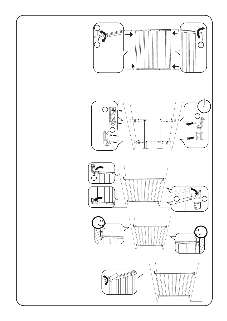
max 60 mm
min 32 mm
max 60 mm
min 18 mm
65 mm
722 mm
86 mm
769 mm
6
7
8
4. Screw both spindles (3) with
a nut (4) on each into one side of
the gate.
Screw both hinge-bars (5) into the
other side of the gate
5. Mark the position for the wall cup (6) and wall catch (7) on the opposite wall surface to
where you want the gate to hinge from. The top hole for the lower wall cup (6) should be 86mm
above the floor. The top hole for the upper wall catch (7) should be 769mm above the floor.
Likewise mark the position for the hinges (8) on the wall surface you want the gate to hinge from.
The top hole for the lower hinge
should be 65mm above the floor.
The top hole for the upper hinge
should be 722mm above the
floor. Fix the wall cup, catch and
hinges using appropriate fixings
depending on the wall surface:
wood screws for wood surfaces,
wall plugs and screws for brick /
concrete / plastered surfaces and
metal screws for metal surfaces.
These screws and fixings are not
provided.
A
4
3
5
6. Place the gate into position,
making sure to insert both of
the hinge bars (5) into the
hinges (8).
Adjust the spindles (3) so that
they fit comfortably into the
wall cup and wall catch.
7. Ensure that the distance
between the gate and the wall
on the latch side is no less than
18mm and no more than 60mm,
and that the distance between the
gate and the wall on the hinge
side is no less than 32mm and no more than 60mm.
Adjust the spindles and/or hinge bars as necessary
to achieve these distances.
8. Use the spanner provided to
tighten the nuts
8
3
5