How to remove the cassette door, How to remove the audio circuit board, How to remove the power supply circuit board – Denon DN-730R User Manual
Page 7
Attention! The text in this document has been recognized automatically. To view the original document, you can use the "Original mode".
t D N - 7 3 0 R I
Meter Circuit Board
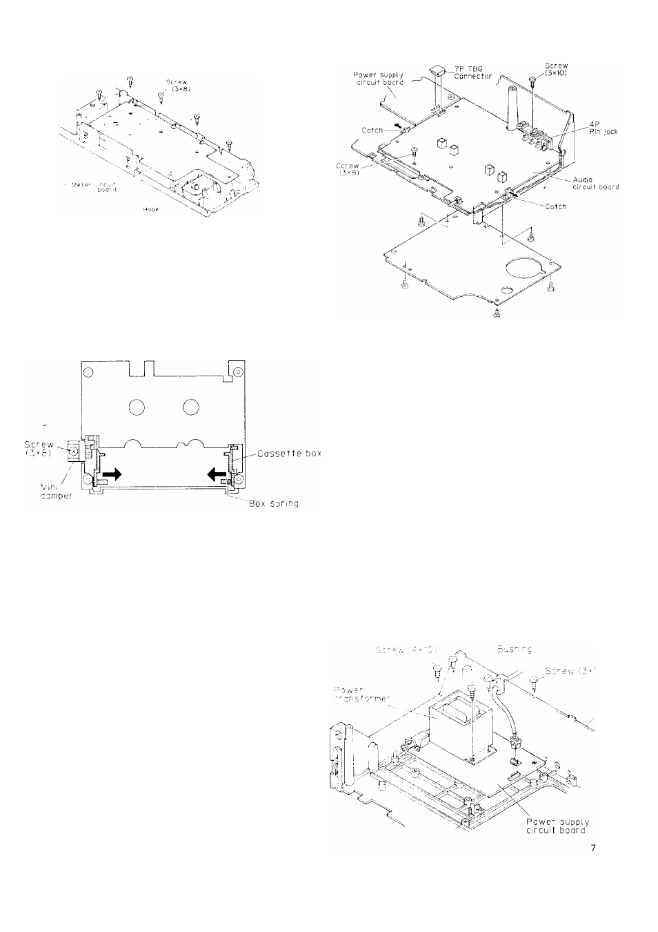
5. How to Remove the Cassette Door
(1 ) Remove the MINIthA'I'JIPER'retaining screw J x 8 CBTS(P)-
B and take out thé MINI DAMPER,
(2) Hold the legs of the CASSETTE BOX folded inwards and
pull up to remove the CASSETTE BOX and BOX SPRING.
Front surface of Front Ass'y
(21
(3)
6. How to Remove the Audio Circuit Board
(1) Remove the top cover and the front panel. (Refer to section
.
1
.)
Remove the front esc. ass'y. (Refer to section 2.)
Remove the connectors from the audio circuit boaid and
power supply circuit board.
Side of the
Side of the
Power supply
CN901 — (7P) — CN901 audio circuit
circuit board
TBG
board
' CONNECTOR
Remove the screw (3 x 10 CBTS-P tight) (3 x B C B T S - S
tight) that is holding down the 4P pin jack and circuit board.
By removing the two catches (left and right) of the chassis
holding down the circuit board in the directions of the
arrows shown below, the audio circuit board can be pulled
forward.
(3)
Note:
• Almost all of the service repairs to the audio cir
cuit board can be performed by removing the
bottom cover on the rear side of the chassis
Only when it IS unavoidable should you refer to
the removal method mentioned above.
• When reassembling, follow the procedures in
the reverse order. However, if each of the various
parts are not assembled properly in their respec
tive position, the sel cannot be assembled in
somie cases. Therefore, check the work of each
step carefully when assembling.
How to Remove the Power Supply Circuit
Board
Remove the top cover and the front panel. (Refer to section
1 )
Remove the bushing that is fixing the power supply cord
from the chassis.
When the five screws ( 4 x 1 9 CBTS-P tight) ( 3 x 1 0
CBTS-P tight) that are holding the power transformer and
chicuit board are removed, the power supply circuit board
can be removed by raising it.
(4)
C r e s s . s