J disassembly instructions j, How to remove the front panel, How to remove the mec hanisms – Denon DN-730R User Manual
Page 6: How to remove the meter circuit board, How to remove the front escutcheon ass'y, Disassembly instructions ~7
Attention! The text in this document has been recognized automatically. To view the original document, you can use the "Original mode".
I D N - 7 3 0 R I
j DISASSEMBLY INSTRUCTIONS j
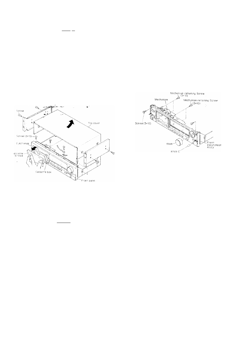
1. How to Remove the Front Panel
(1i Remove the four screws, (4 X 12. CBTS-P) in the side of the
top cover. Move the top cover to the rear and rise it to
remove it.
(2) Press the eject knob, open the cassette box and remove the
cassette window as shown in the figure.
.
Note:
Handle the cassette window with care because it
can be scratched easily.
(3' Remove the three screws ( 3 x 1 0 CBTS-P) on top of the
front panel, the two hooks on the top, the three hooks on
the bottom and pull the unit forward to detach it.
Meter circuit
board
Audio
circuit
board
(3) Disconnect all lead connectors.
C Mechanism ( W151 (7P) — CN151 '
I
Head wire — CN301
1
Head wire — CN302
I W131 (3P) - CN131
1
23PFFC-CB121 .
Remove Volume Knob and Volume Knob (C).
Remove the four retaining screws (2 6 x 6 CBTS(Si)-Z) (3
X
10 CBTS(P)-B) holding the Mecha Bracket.
Remove the Hooks at the left and right of the f 'ont face of
the Front Esc. Ass'y, and the two hooks on the bottom.
Front Ass'y can be removed towards the front.
(4)
(5)
(
6
)
Hooks at left and right of Front Esc. Ass'y
3. How to Remove the Mec hanisms
Remove the four Mechanism retaining screws 3 x 1 0 CBTS(P)-B
and lake out C Mechanism.
T
2 hooks on the top of the front panet
m,...i. i. .... a
_ _____________0_
T
4. How to Remove the Meter Circuit Board
(1) Remove the top cover and the front panel. (Refer to section
1
.)
(2) Remove the front esc. ass'y, (Refer to section 2.)
(3) If you remove the five binding screws ( 3 x 8 CBTS -P tight)
of the meter circuit board, and loosening the five hooks, the
meter circuit board can be taken off.
Note; When replacing the tact switch, check to make sure
that
It
is not floating above the circuit board. If it is
floating, the switch will oe in the on condition when
the set is assembled
3 hooks on the bottom of the front panel
o
X
2. How to Remove the Front Escutcheon Ass'y
(1) Remove the top cover and front panel. (Refer to Step 1 )
(2) Remove the three retaining screws 3 x 1 0 CBTS-(P)-B
holding the Front Escutcheon at the front.