Alarm card connection guidelines, The router is equipped with two alarm cards, Figure 2-17 alarm card connector location – Cisco XR 12416 User Manual
Page 33: Caution
2-33
Cisco XR 12416 and Cisco XR 12816 Router Chassis Installation Guide
OL-17440-01
Chapter 2 Preparing for Installation
Alarm Card Connection Guidelines
Alarm Card Connection Guidelines
The router is equipped with two alarm cards:
•
One alarm card occupies the dedicated far left slot in the upper card cage
•
The second alarm card occupies the dedicated far right slot in the lower card
cage
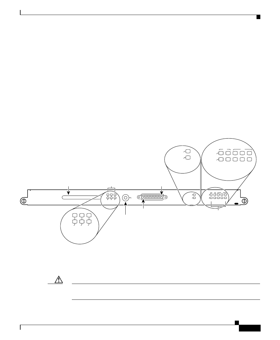
Each alarm card has one 25-pin D-subconnector (ALARM) on the front panel that
connects the router to an external site alarm maintenance system (
).
When a critical, major, or minor alarm is generated, it energizes the alarm relays
on the alarm card to activate the external site alarm.
Figure 2-17
Alarm Card Connector Location
The alarm relay contacts on the alarm card consist of standard common, normally
open, and normally closed relay contacts that are wired to the pins on the
connectors.
Caution
Only safety extra-low voltage (SELV) circuits can be connected to the alarm
connector. Maximum rating for the alarm circuit is 2 A, 50 VA.
ACO/L
T
ALARM
CSC
0
FA
IL
1
0
1
2
ENABLED
ENABLED
FA
IL
CRITICAL
MAJORMINOR
SFC
ALARM
26867
Pin 25
Audio alarm
cutoff switch
Pin 1
Handle
Critical, major, and
minor alarm LEDs
Clock and scheduler card
and switch fabric card LEDs
ENABLED
FAIL
CSC
0
FAIL
1
0
1
2
ENABLED
CRITICAL
MAJORMINOR
SFC