Page 2 – Honeywell T6051 User Manual
Page 2
Attention! The text in this document has been recognized automatically. To view the original document, you can use the "Original mode".
2. Mount the 2 by 4 inch outlet box either vertically
or horizontally, as desired.
3. Run conduit between the outlet box, power source,
and the unit being controlled. Leave about six inches of
wire in the box for connections. (Refer to the WIRING
section for the number of wires required.)
4. Place the mounting plate on the outlet box either
vertically or horizontally. Insert the two furnished
mounting screws, leaving them loose enough to move
the mounting plate for leveling. See Fig. 2.
5. Level the mounting plate and tighten the mounting
screws. (See Fig. 2.)
6. Connect the heating and/or cooling system wires
or the Series 60 equipment wires to the back terminals
of the thermostat. See Figs. 3—10.
7. When wiring is complete, secure the fiber insulator
by snapping the holes in the flap over the switch rivet
heads. When the normally open terminal is used, clip the
flap to allow it to pass around the wire.
8. Hang thermostat on mounting plate tabs, see
Fig. 2.
9. Take socket-head cover mounting screw (furnished)
and insert it in tab at bottom of base. Do not tighten.
Replace cover.
10.
Insert set point knob into socket-head screw and
tighten. This fastens cover and thermostat to the mount
ing plate previously attached to outlet box. Remove knob.
WIRING
CAUTION
Disconnect power supply before making wiring
connections to prevent electrical shock and
equipment damage.
All wiring must agree with local electrical codes and
ordinances. Refer to the wiring diagrams below, instruc
tions packed with the subbase, and heating and/or cooling
equipment manufacturer's instructions.
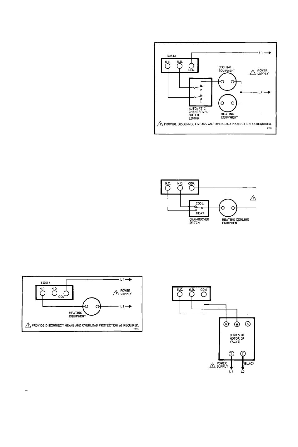
Fig. 3—T6051A used in heating only application.
N.C.
N.O
O ‘
cooLmc
EQUIPMENT.
O'
A
POWER
SUPPLY
/i\ PROVIDE DISCONNECT MEANS AND OVERLOAD PROTECTION AS REQUIRED.
Fig. 5-T6051A heating-cooling control for separate
heating and cooling equipment.
POWER
SUPPLY
/^PROVIDE DISCONNECT MEANS AND OVERLOAD PROTECTION AS REQUIRED.
Fig. 6—T6051 heating-cooling control with changeover
switch for combination heating-cooling
equipment.
A
PROVIDE DISCONNECT MEANS AND OVERLOAD PROTECTION AS REQUIRED.
Fig. 4—T6051A used in cooling only application.
Fig. 7—T6051 used as a series 60 control. 3-wire, line
voltage, two position control.
Page
2