Installation instructions (cont’d), Venting (cont’d) gas piping, Awarning – Kenmore POWER MISER 153.336851 User Manual
Page 14
Attention! The text in this document has been recognized automatically. To view the original document, you can use the "Original mode".
Installation Instructions (cont’d)
Venting (cont’d)
Gas Piping
All vent gases must be completely vented to the outdoors of the
structure (dwelling). Install only the draft hood provided with
the new water heater and no other draft hood.
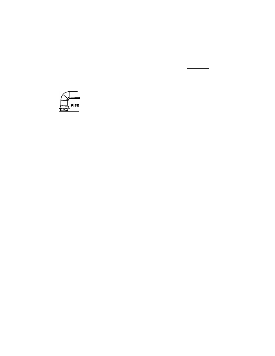
Vent pipes must be secured at each joint with sheet metal screws.
MIN. % INCH
PER LINEAR
FOOT
TO
CHIMNEY
VENT PIPE INSTALLATION
There must be a minimum of 6" clearance between single wall
vent pipe and any combustible material. Fill and seal any clear-
single wall vent pipe and combustible material
with mortar mix, cement, or other noncombustible substance.
For other than single wall, follow vent pipe manufacturers clear
ance specifications. To insure a tight fit of the vent pipe in a
brick chimney, seal around the vent pipe with mortar mix
cement.
AWARNING
Mate sure the gas supplied is the same type listed on the
mc^d rating plate. The inlet gas pressure must not exceed
10.5 in. water coiumn (2.6kPa) ior natural gas or 13 in. water
column (3.2kPa) for propane (LP.) gas. The minimum miet
gas pressure listed on the model rating plate b for the pur^
pose of input adjustment
AWARNING
If the gas control valve b subjected to pressures exceeding
'A
pound per square inch (3.5kPa), the damage to the gas con
trol valve could result in a fire or explosion from leaking gat
AWARNING
If the main gas line shutoff serving all gas appliances b used,
also turn “OFF" tte gas at each appliance. Leave all gas appli
ances shut off until the water heater installation b complete.
AWARNING
Failure to have required clearances between vent piping and
combustible material will result in a fire hazarxl.
AWARNING
Be sure vent pipe b properly connected to prevent escape of
dangerous flue gases which could cause deadly asphyxiation.
AWARNING
Chemical vapor corrosion of the flue and vent system may
occur if air for combustion contains certain chemical vapors.
Spray can propellants, cleaning solvents, refrigerator and air
conditioner
r^^rants,
swimming
pool chemicals, calcium
and sodium chloride,
waxes,
bleach, and process chemicals are
typical compounds which are potentially corrosive.
A gas line of sufficient size must be run to the water heater.
Consult the latest edition of National Fuel Gas Code ANSI
Z223.1, also referred to as NFPA54 and the gas company concern
ing pipe size.
There must be:
• A n^ly accessible manual shut off valve in the gas supply line
serving the water heater, and
• A drip W (sediment trap) ahead of the gas control valve to help
prevent mtt and foreign materials from entering the gas control
valve.
• A flexible gas connector or a ground joint union between the
shutoff valve and control valve to permit servicing of the unit.
Be sure to check all the gas piping for leaks before lighting the
water heater. Use a soapy water solution, not a match or open
flame. Rinse off soapy solution and wipe dry.
Standard Modeb are for installation up to 3,300 feet above sea
level.
High Altitude Modeb are for installation from 3,300 to 5,500
feet above sea level.
If a standard model is installed above 3,300 feet or a high altitude
model is installed above 5,500 feet, the input rating must be
reduced at the tate of 4 percent for each 1,000 feet above sea level.
Contact your local Scars Service Center or gas utility for further
information.
14