Heating-only system, Heating/cooling system, Typical wiring diagrams – Honeywell Y8185 User Manual
Page 6: Cautions
Attention! The text in this document has been recognized automatically. To view the original document, you can use the "Original mode".
12 CHECK OUT THERMOSTAT OPERATION'
□
CAUTIONS
Do NOT check operation by shorting across ter
minais of relay or valve coil; this will burn out the
thermostat heat anticipator.
HEATING-ONLY SYSTEM
HU
Turn on power to the furnace.
[Z] Push both temperature setting levers together at
least 5 F [3 C] above room temperature. The main
burner should come on. The fan will start when the fur
nace heats up.
□
Move both levers 5 F [3 C] below room tempera
ture. The burner should shut off.
Q Operate the entire heating system at least one
oompíete cycle.
D
IF THERMOSTAT FAILS ANY TEST, REFER TO
TROUBLESHOOTING
GUIDE
IN
THE
OWNER'S
MANUAL.
□
Reset both temperature setting levers to desired
temperatures.
HEATING/COOLING SYSTEM
n Turn on power to the furnace and cooling system.
n Place the system switch lever at HEAT and fan
switch lever at AUTO.
[m Push both temperature setting levers together at
least 5 F [3 C] above room temperature. The main
burner should come on. The fan will start when the fur
nace heats up. (If central electric heat system, fan starts
immediately.)
Move both levers 5 F [3 C] below room tempera
ture. The burner should shut off.
□
Place the system switch lever at COOL and the
fan switch lever at AUTO. The cooling equipment should
operate, and the fan will start. Allow for any time delay
that may be built into the compressor control circuit.
NOTE: To avoid compressor damage, do not operate
the system if outdoor temperature is below 50 F
[10 0]. Refer to manufacturer’s recommendations.
□ Move both temperature setting levers together at
least 5 F [3 C] above room temperature. The cooling
equipment should shut off.
□
Place the fan switch at ON. The fan should run
continuously with the system switch in any position.
HH Place the system switch at OFF. Move both
temperature setting levers to various positions. The
heating and cooling systems should not operate.
□
Operate the entire system for at least one com
plete cycle with the system switch at COOL and one
complete cycle with the switch at HEAT.
D IF THERMOSTAT FAILS ANY TEST, REFER TO
TROUBLESHOOTING
GUIDE
IN
THE
OWNER'S
MANUAL
□
Reset both temperature setting levers to desired
temperatures.
LEAVE OWNER’S MANUAL, ASSISTANCE INFORMA
TION, AND REPLY CARD IN A CONVENIENT PLACE
FOR THE BUILDING OCCUPANT OR PROVIDE WITH
OTHER APPLIANCE MANUALS.
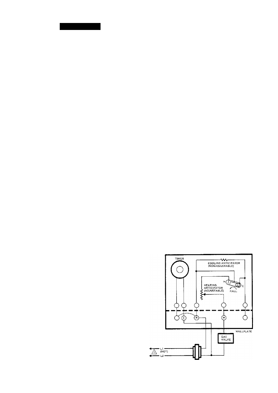
TYPICAL WIRING DIAGRAMS------------------
Follow the hookup diagram supplied with your heat
ing or heating/cooling equipment. If not available, use
the following diagrams as a guide.
REMEMBER: Your wiring must follow local electrical
codes and ordinances.
THERMOSTAT
Ai
Fig. 11 —Hookup showing a typical 24 V, gas heating
control system.