Checkout, Thermostat, Setting – Honeywell CT52A User Manual
Page 5
Attention! The text in this document has been recognized automatically. To view the original document, you can use the "Original mode".
3^1
CT53
WIRE AND MOUNT THERMOSTAT (continued)
□
Recheck for level position
ing, and firmly tighten both
mounting screws.
□
If installing CT50A, CT51 A,
or CT52A, make sure you
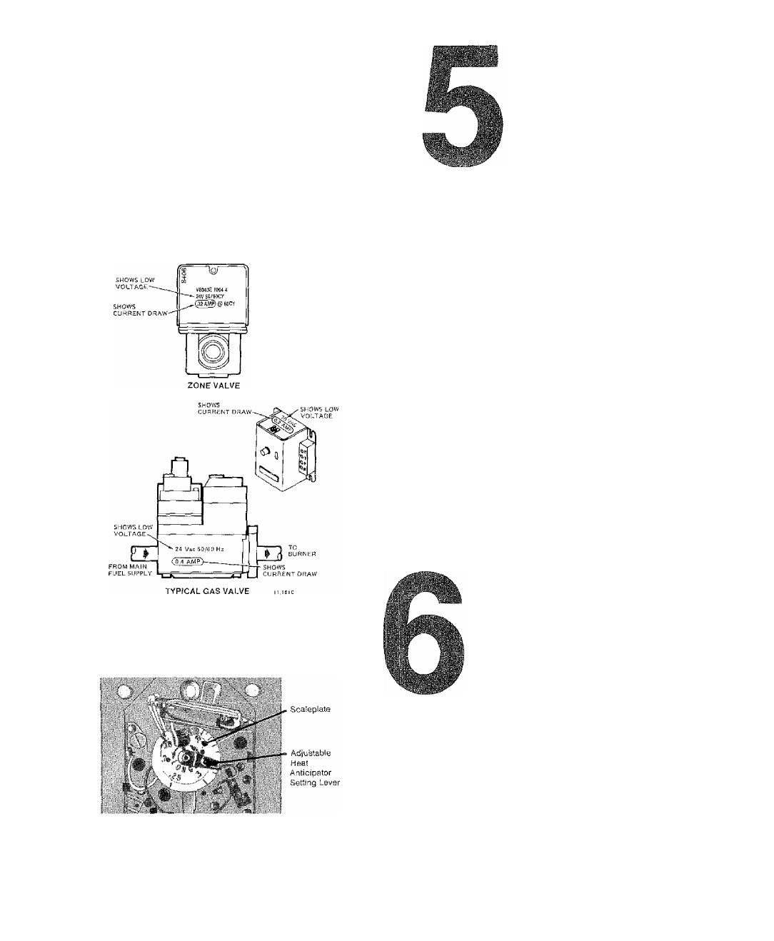
have the current (anticipator
setting) for your system. This is
the number you wrote in the box
in step 3. If you were unable to
find the current draw for step 3,
this
information
can
be
found
printed on the primary control at
the furnace. The primary control
is usually a gas valve, zone valve,
or a relay or burner control box
with the thermostat wires con
nected to it.
jncfi
OIL BURNER CONTROL
□
On the CT50A, CT51A, or
CT52A, set heat anticipator
indicator at rating printed on
primary control.
CHECKOUT
THE
THERMOSTAT
□
On the CT51A, the system
switch controls as follows:
HEAT—heating system only
operates.
. OFF—heating and cooling sys
tems are disconnected.
COOL—cooling system only
operates.
The
fan
switch
controls
as
follows:
AUTO—fan
operates
when
heating or cooling system,
operates.
ON—fan
operates
continu
ously.
□
NOTE: In the following instruction,
disregard
heating
or
cooling
directions if not applicable to
your system.
Turn
on
power
to
the
heating/cooling system.
□
Observe system operation
for at least one cycle on
both heating and cooling. To
observe:
□
Place the system switch
at HEAT position and fan
switch at AUTO. More the temper
ature setting lever 10 F [5.6 C]
above
room
temperature.
The
heating
equipment
should
turn
on, A short warm-up period may
be required before the system
fan turns on.
□
Place system switch at
COOL position and move
temperature setting lever 10 F
[5.6 C[ below room temperature.
The
cooling
equiprnent
should
turn on and the system fan should
turn on,
NOTE: Some systems have a time
delay that can prevent opera
tion up to 30 seconds.
□
Turn the fan switch to ON.
The system fan should turn
on,
and
operate
continuously.
The system blower should con
tinue to operate at any system
switch or thermostat setting.
THERMOSTAT
SETTING
□
On CT51A, place the sys
tem and fan switches at
the desired settings for operation.
□
On all models, move the
temperature setting lever
to the desired temperature com
fort level.
(See ill
4 to hf
heat a|
Press the thermostat cover
firmly onto the mounting