Parts & repair services – Kenmore SF22-804 User Manual
Page 4
Attention! The text in this document has been recognized automatically. To view the original document, you can use the "Original mode".
Date: 12/28/07
Parts & Repair Services
SF22-804
Page 4 of 6
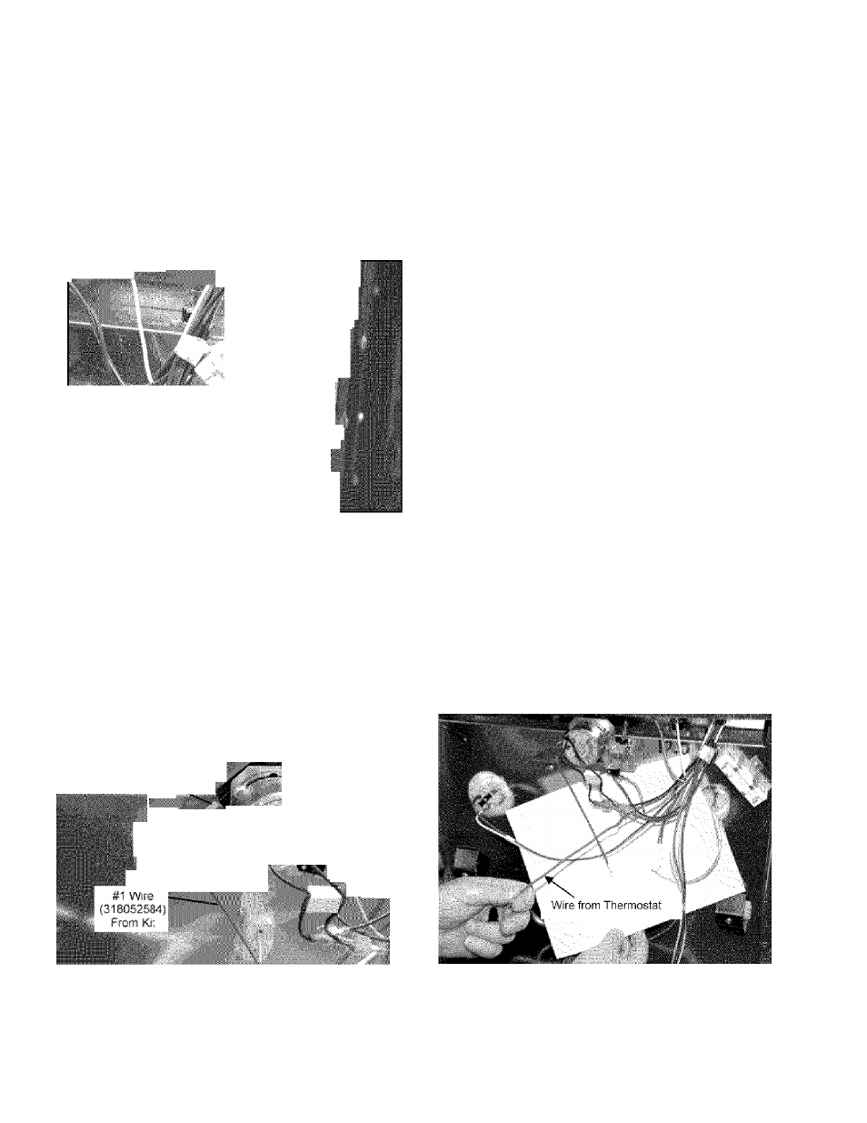
7. Install the resistor on the rear wall as
shown in the photo. Carefully punch or
drill a starter hole for the screw if
necessary.
r
____________
■
fc, ■"
*
_________
8
.
Use existing screw holes to install the
new 120° thermostat to the left of the
existing 170° thermostat. Mark the
chassis with an “X “or “120” to identify
the new thermostat.
9. Install wire # 1 (318052584) onto the
“C” terminal of the new switch. This
wire has a push on terminal on one
end and is stripped on the other end.
\ V ^
^
............. _
...
10. Disconnect the power wire from the
170° thermostat, cut off the terminal
connector and strip approx. 3/16 inch
of the insulation. The power wire is
the one that does not connect to the
fan motor.
Confidential Information -For Internal Use Only
DEPARTMENT 702HSX - Leo Steinys
DEPARTMENT 702PSO - Bob Vondale