Awarning, Gas piping with flexible connector, Gas piping with all black iron pipe to gas control – Kenmore 153.337002 User Manual
Page 16: Installation instructions (cont’d), Gas piping (cont’d)
Attention! The text in this document has been recognized automatically. To view the original document, you can use the "Original mode".
Installation Instructions (cont’d)
Gas Piping (cont’d)
CORRECT GAS PIPE SIZE FOR
WATER HEATERS OPERATING ON NATURAL GAS
Based on Inlet Gas Pressures of 0.5 psig or Less and
a Pressure Drop of 0.3 inches Water Column.
(Based on a 0.60 Specific Gravity Gas)
TOTAL INPUT*
BTU/HR
DISTANCE TO METER, IN FEET
20
30
60
90 1 125
150
200
75,000
'h
Vi
Vi 1
1
1
100,000
V.
Vi
1 1
1
1
150,000
1
1 1 I7i
iVi
I7i
*Of all gas appliances in line.
A gas line of sufficient size must be run to the water heater.
Consult the latest edition of National Fuel Gas Code ANSI
Z223.1, also referred to as NFPA 54 and the gas company con
cerning pipe size.
There must be;
• A readily accessible manuil shut off valve in the gas supply line
serving the water heater, and
• A drip leg (sediment trap) ahead of the gas control valve to help
prevent dirt and foreign materials from entering the gas control
valve.
• A flexible gas connector or a ground joint union between the
shutoff valve and control valve to permit servicing of the unit.
Be sure to check all the gas piping for leaks before lighting the
water heater. Use a soapy water solution, not a match or open
flame. Rinse off soapy solution and wipe dry.
Standard Models are for installation up to 3.300 feet above sea
level.
High Altitude Models are for installation from 3,300 to 5,500 feet
above sea level.
If a standard model is Installed above 3,300 feet or a high altitude
models is installed above 5,500 feet, the input rating must be
reduced at the rate of 4 percent for each 1,000 feet above sea level.
Contact your local Sears Service Center or gas utility for further
information.
AWARNING
The appliance and its gas connection must be ieak tested
before placing tiie appliance in operation.
AWARNING
’ The appliance and its individual shutoff valve must be discon
nected from the gas supply piping system during any pressure
testing of the gas system at test pressures in excess of
%
pound per square inch (3.5kPa).
• The appliance must be isolated from the gas supply piping sys
tem by closing its individual manual shutoff v^ve during any
pressure testing of the gas supply piping system at test pres
sures equal or less than Vi pound per square inch (3.5kPa).
AWARNING
Use pipe joint compound or teflon tape marked as being
resistant to the action of petroleum [Propane (LP.)] gases.
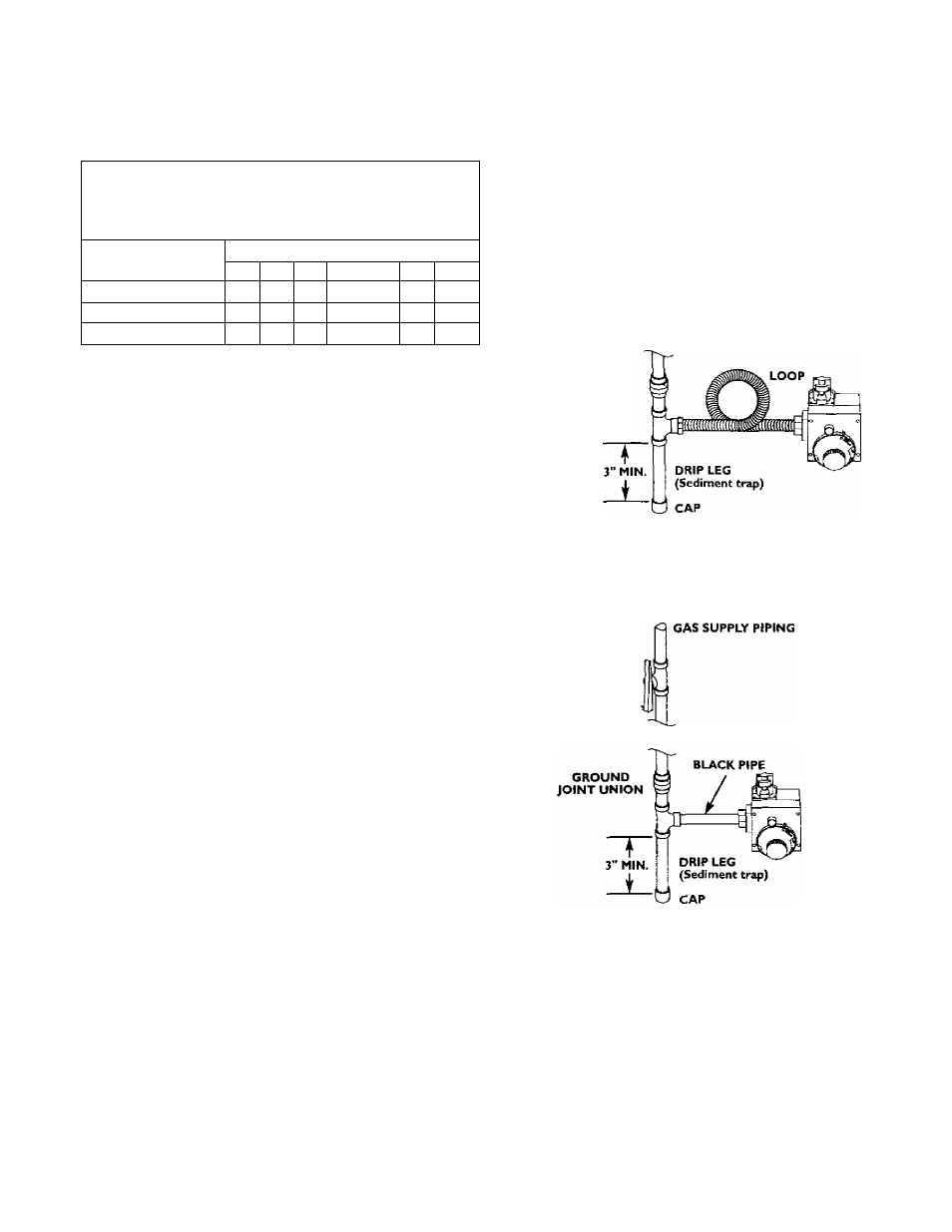
GAS PIPING WITH
FLEXIBLE CONNECTOR
fq GAS SUPPLY PIPING
MANUAL
SHUTOFF
VALVE
FLEXIBLE GAS CONNECTOR
LABELED AS COMPLYING
WITH ANSI STANDARDS
GROUND JOINT
UNION (Optional)
GAS
CONTROL
VALVE
GAS PIPING WITH ALL BLACK IRON
PIPE TO GAS CONTROL
MANUAL
SHUTOFF
VALVE
GAS
CONTROL
VALVE
AWARNING
Contaminants in the gas lines may cause improper operation
of the gas control valve that may result in fire or explosion.
Before attaching the gas line be sure that all gas pipe is clean
on the inside. To trap any dirt or foreign materiiU in the gas
supply line, a drip leg (sometimes called a sediment trap)
must be incorporated in the piping. The drip leg must be
readily accessible. Install in accordance with the “Gas Piping”
section. Refer to the latest edition of the National Fuel Gas
Code, ANSI Z223.I, also referred to as NFPA 54.
16