Kenmore POWER MISER 153.320661 User Manual
Page 15
Attention! The text in this document has been recognized automatically. To view the original document, you can use the "Original mode".
The length in any ground return path does not exceed
6 feet.
The
circuit
conductors contained therein
are
protected
by overcurrent devices rated
at
20 amperes or less.
The conduit or tubing is terminated in fittings approved
for
grounding.
NOTE: If you have purchased a three wire connection wafer
heater but you are not on a “Time Clock” or “Off Peak” meter
and
have a
standard two wire
connection power
supply,
simply follow the connection diagram in
block
3 of the three
wire connection diagram.
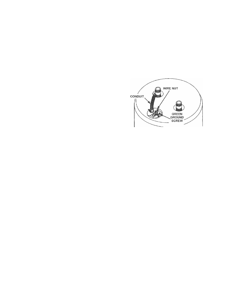
6.
Use wire nuts and connect
the
power supply wiring to the
wires inside
the
water
heater’s
junction box.
For
complete
grounding
details and
all allowable
exceptions,
refer to the current edition of the NEC - National Eiectrical Code
NFPA70.
4. A standard 1/2"
conduit
opening has been made in the water
heater junction box for the conduit
connection.
5. Wiring Diagrams, see
“ W ir in g D ia g r a m s ”
section have
been
supplied
showing
the
two
most
common
types
of
connections between the water heater and the power supply.
You can easily
see
which type
connection
you have by
removing the junction box cover on top of the water heater.
•
Two Wire Connection Diagrams: is the most common
requiring you to simply connect red
to
red,
black
to
black, and
the ground wire
to
the green
ground
screw
in the junction box of
the wafer heater.
•
Three Wire Connection Diagram: is used when you
are
connecting
the water
heater
to a power supply
that has a “Time Clock” or “Off Peak” meter. To make
these
connections
refer
to block 1 or 2 in this wiring
diagram for
the
type of
system
you
have.
7. The water heater must be electrically “grounded” by the
installer, A
green
ground
screw
has
been
provided on the
water heater’s junction
box.
Connect ground wire to
this
location.
8.
Replace
the wiring junction
cover
using the
screw
provided.
FIGURE 23.
15