Temperatyre-pressure relief valve, Installation instructions (cont’d), A warning – Kenmore 153.327366 User Manual
Page 9: Awarning
Attention! The text in this document has been recognized automatically. To view the original document, you can use the "Original mode".
Installation Instructions (cont’d)
Temperatyre-Pressure
Relief Valve
A WARNING
At the time of manufacture this water heater was provided
with a combination temperature-pressures relief valve cer
tified by a nationally recognized testing laboratory that
maintains periodic inspection of production of listed equip
ment or materials, as meeting the requirements for Relief
Vaives and Automatic Gas Shutoff Devices for Hot Water
Supply Systems, and the current edition of ANSI Z 2 1 . Ï 2
and the code requirements of ASME. If replaced, the valve
must meet the requirements of local codes, but not less
than a combination temperature and pressure relief vaive
certified as meeting the requirements for Relief Valves and
Automatic Gas Shutoff Devices for Hot Water Supply
Systems, ANSI Z2I.22 by a nationally recognized testing
laboratory that maintains periodic inspection of production
of listed equipment or materiais.
The valve must be marked with a maximum set pressure
not to exceed the marked hydrostatic working pressure of
the water heater (ISO lbs. p.s.l.) and a discharge capacity
not less than the water heater input rate as shown on the
model rating plate. (Electric heaters - watts divided by
1000
X
34
i
2 equal BTU/Hr. rate.)
Your local jurisdictional authority, while mandating the use
of a temperature-pressure relief valve complying with
ANSI Z2I.22 and ASHE, may require a valve model differ
ent from the one furnished with the water heater.
Compliance with such local requirements must be satisfied
by the installer or end user of the water heater with a
locally prescribed temperature-pressure relief valve
installed in the designated opening in the water heater in
place of the factory furnished valve.
For safe operation of the water heater, the relief vaive
must not be removed from It's designated opening or
plugged.
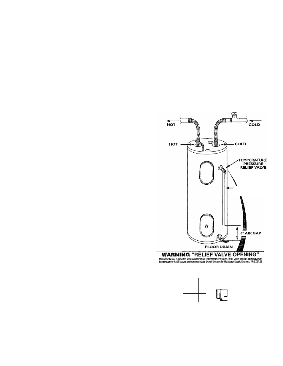
The temperature-pressure relief valve must be installed
directly into the fitting of the water heater designated for
the relief valve. Position the vaive downward and provide
tubing so that any discharge will exit only within 6 inches
above, or at any distance below the structural floor. Be cer
tain that no contact is made with any live electrical part.
The discharge opening must not be blocked or reduced in
size under any circumstances. Excessive length, over 30
feet, or use of more than four elbows can cause restriction
and reduce the discharge capacity of the valve.
No valve or other obstruction is to be placed between the
relief valve and the tank. Що not connect tubing directly to
discharge drain unless a 6 air gap is provided. To prevent
bodify injury, hazard to life, or property damage, the relief
valve must be allowed to discharge water in quantities
should circumstances demand. If the discharge pipe is not
connected to a drain or other suitable means, the water
flow may cause property damage.
The Discharge Pipe:
* Must not be smaller in size than the outlet pipe size of
the vaive, or have any reducing couplings or other
restriction.
* Must not be plugged or blocked.
* Must be of material listed for hot water distribution,
* Must be installed so as to allow complete drainage of
both the temperature-pressure relief valve, and the dis
charge pipe.
* Must terminate at an adequate drain.
* Must not have any vaive between the relief valve and
AWARNING
The temperature-pressure relief valve must be manually
operated at least once a year. Caution should be taken to
ensure that (I) no one is in front of or around the outlet
of the temperature-pressure relief valve discharge line,
and (2) the water manually discharged will not cause any
bodily injury or property damage because the water may
be extremely hot
If after manually operating the valve, it fails to completely
reset and continues to release water, immediately, close
the cold water inlet to the water beater, follow the drain
ing instructions, and replace the temperature-pressure
relief valve with a new one.
DISCHARtSe PIP6
(Di> cap or piu|f)
Уш btaljurtsdsülwal шдЬогйу,
Ihe d a
№( Valva œn^ng
Ш
ANS
¿2\
,22 йгй ASMS,
ту
э
diefad Irom
хЫ
Stimlshsi wsthlha ìisaifif.
C«i^
2
f
№8
wiEh sudi beai
misi Ise saiMed by she InsfàiïGf ш
mû
of the
шт
wi8i
a locally prescribed Tsmperaiuie-f^ressuis Rdiet Vdv6 lnsìaSetì
in
die
opsorng In
Ш mm
TfiP HEUEF
VALVE PROBE
MUST EXTEND
f^rrQTA^ЗK
TANK г ;
'¡\
TANK
¿ÿii
FiTTING
JFi
BRASS
^
NIPPLE
T4P
SHANK
tENSTH
• If a short
shank {less
llwi
?*) iGroporalLfre-pmssurB
je
II
b
I
vaive
is
lo ba
Inslaflad
las shown), a
nipple end cotiding must
be
used
■
f{ a
long shank
{2* or loi^sr) is fo to
Instalisif, do
fwf use
fhs nipple
and coupling.
'liisIÉI Tcmi^muire-PfcssuFe
equipinenl requìrad by codes, bu! rtd fóss
Шап
b combina'
lion TempeEalEife-Pisssu/B Raliol Valve certifiMf as moaling Iha ieqdiamSRts fot RelìeI VBhffiS arid
AtSoipaiic QasSiHfloli Devices lof Hd-Waier Supj^y Syslems, ANS 221.22 by a faiìùnailyfecogffeed lesi-
lag laboialory ^al nsaBiìdrre peiìedJs laspectìan oi pfodutiion d llstsd equlpniSRi or maisdals. TìiB valve
musi ¿0 pfianisd, pfo^inJ w!h itidng, or othErwfso InsiaHed so Ihal dischai^ cafi йхЙ
wìdiifi
5 IfiCftss
or al any dstan&e boknv tha sbudural Hoor, ami cannai confaci any Uva еЫг1сг1 pad.*
Por sda operdbn oi Ibe water Iwaler, tfis Relig} Valva
япей
noi
ba reniowid or
Sea rranuai heading - ■^Temj^faiure-Pisssura Rdi&f Valva* ier inslallallon ano mfilnlDnancB of RelieJ
Valve, discharga pif® dher saieiy piscairtloRs.