Installation – GE 2-9730 User Manual
Page 8
Attention! The text in this document has been recognized automatically. To view the original document, you can use the "Original mode".
INSTALLATION
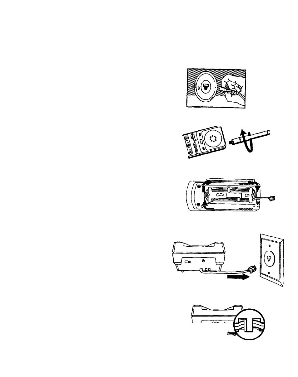
A modular (Universal Service Order Code) USOC:
RJ11C outlet jack (illustrated) is required.
Installation of this telephone in locations with 4-prong
jacks or with hard-wired outlets will require additional
Converters (not included). The dealer from whom
you purchased your phone or a telephone supply
store can advise you regarding the proper Converter.
Installation
Note:
Some
cordless
telephones
operate at frequencies that may cause interference
to
nfiflrhv TVc anrf Vr:De-
tn min imi^^
r\r
fNrAt/rt»-»*
v^i iv»
\j\ pi^vdli
such interference, the base of the cordless telephone
should not be placed near or on top of a TV or VCR;
and, if interference is experienced, moving the
cordless telephone farther away from the TV or VCR
will often reduce or eliminate the interference.
1. Insert anienna and screw into place.
2. This telephone is equipped with a Cord Wrap
for the straight UNE TELEPHONE CORD.
This Cord Wrap is located on the bottom of
the BASE. '
Wrap TELEPHONE UNE CORD around cord
wran Ipauinn pnrinnh nf nnrH
f r a a t n
rnonh
...
wi
iVi/ I
i
outlet jack.
3. Plug TELEPHONE STRAIGHT CORD into
Modular wall jack.
4. Plug the smaller, “L” shaped end of the AC
ADAPTER into back of unit.
AC POWER SUPPLY CORD must be fed
through the STRAIN RELIEF on bottom of
base to prevent cord slippage, (see inset).
Note; Use only GE AC ADAPTER and
POWER SUPPLY CORD Model #5-2346 with
this oroduct.
A.
Telephone Outlet
Requirements
B.
Quick Set-up