I before – Whirlpool Thin Twin User Manual
Page 5
Attention! The text in this document has been recognized automatically. To view the original document, you can use the "Original mode".
Numbers
correspond
to steps.
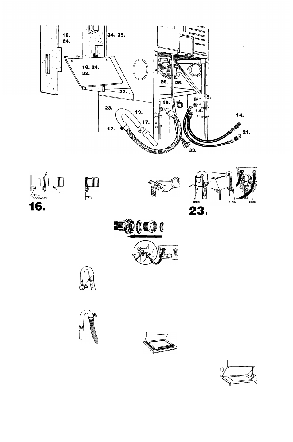
IMPORTANT: THIS PROCEDURE MUST BE
FOLLOWED TO ASSURE PROPER INSTALLATION.
19
clamp
drain
hose
1/4"
■(.64 cm)
max.
I Put "hook" end of drain
hose into iaundry tub or standpipe. Check for
proper iength of drain hose.
CHECK THAT DRAIN HOSE IS NOT TWISTED
OR KINKED AND IS SECURELY IN PLACE.
A
B
___
20
1/4"
64 cm)
max.
I To prevent the drain hose
from coming off or ieaking, if must be
installed per the following instructions:
1. Wet the inside end of the drain hose with
tap water. DO NOT USE ANY OTHER
LUBRICANT.
2. Squeeze ears of small clamp with pliers to
open clamp and place clamp over end
of drain hose.
3. While holding clamp open, work end of
drain hose onto drain connector.
4. Position clamp over the drain hose area
marked "clamp." Release clamp, Clamp
should bel /4 inch (.64 cm) from end of
drain hose.
I Before
attaching water inlet
hoses, run water through
both faucets into a
bucket. This will get rid of
any particles in water lines
that might clog hoses. Mark which is the hot
water faucet.
coupling
larger
faucet
smaller
washer adapter washer
Inlets are plastic.
DO NOT STRIP OR
CROSSTHREAD.
cold
17
21
.
I standpipe or laundry
tub drain system: Open hose
clamp and slide over "hook"
end of drain hose to secure the
rigid and corrugated sections
together.
Floor drain system;
Do Not install "hook" end of drain hose fo
corrugated section. Consult your plumber for
proper installation.
If drain hose does not fit Into
standpipe, install adapter. Open
other hose clamp with pliers and
place clamp over rigid end of
drain hose.
Insert tapered end of adapter
into rigid end of drain hose up to
stops on the sides of adapter.
Secure with clamp.
Slide wosher/dryer onto cardboard or
hardboard before moving across floor to
avoid damaging floor.
• For both Inlet hoses; Insert larger washer
into end of coupling; then attach faucet
adapter. Insert smaller washer into end of
faucef adapfer.
• Make sure washers are firmly seated into
couplings.
• Attach bottom hose with adapter (inlet
marked "H") to hot water faucet. Attach
top hose with adapter (inlet marked "C")
to cold water faucet,
• Tighten couplings to faucets by hand; then
use pliers to make final two-fhirds turn.
• Do Not overtighten; this could cause
damage to coupler.
Move wosher/dryer fo ifs permonenf
posifion. Remove cordboord/hordboard
from under wosher/dryer.
I Make sure the "hook" end of
drain hose is in laundry tub or standpipe. Wrap
the plastic beaded strap around the drain
hose and laundry tub or standpipe. Thread
beaded end of sfrap through keyhole end. Pull
until strap is tight. Slide strap into narrow end of
keyhole to lock strap in place. See Figures A-B.
If the water inlet faucets and drain standpipe
are recessed, tightly wrap the plastic beaded
strap around the drain hose and faucet body.
(Do Not wrap strap around the faucet handles
or stems.) Thread beaded end of strap through
keyhole end. Pull until strap is tight. Slide strap
into narrow end of keyhole to lock strap in
place. See Figure C.
Secure the drain hose to
the laundry tub or
standpipe with the plastic
beaded strap. Failure to
properly secure drain hose
could result In water
damage.
If drain hose cannot be strapped Into place,
hose must be cut exactly to length so “hook”
end Is held ttghtty over edge of laundry tub or
standpipe. See Figure D.
If a longer drain hose is needed, drain hose. Part
No. 388423 and Fiose Connection Wt, Part No.
285442 are available from your authorized parts
distributor. If draih hose must be shortened, use
Hose Connection Kit, Part No. 285442.
Note: If wosher/dryer Is moved to adjust drain
hose, the wosher/dryer must be leveled again.
Repeat Step 22. Place cardboard under the
wosher/dryer and carefully move wosher/dryer
to avoid damaging floor covering.
18
I If you have room to work from
either side of the washer/dryer, move
washer/dryer close to final position so you
can easily complete the installation steps.
If you are working In a closet or recessed
area, move the washer/dryer into final
position and remove cardboard/hardboard
from under washer/dryer. Remove the two
foam shipping pieces between the washer
and dryer and place with the other shipping
pieces. Remove the two Phillips-head screws
located at the top of the access panel. (See
illustration for Sfep 24). Remove access
panel and set access panel and screws
aside. Complete the following steps through
the access area.
Panel D
I Carefully move the
washer/dryer into final position.
• Tilt the washer/dryer forward, raising back
legs 1 inch (2.5 cm) off the floor so fhat the
rear self-leveling legs will adjusf. Genfly
lower the washer/dryer to the floor.
• Check fhaf the washer/dryer is level by
placing a carpenter's level on top of the
washer, first side to side, then front to
back.
— If it is not level, adjust the front legs up or
down.
— Tilt the washer/dryer forward, raising back
legs 1 inch (2.5 cm) off the floor so that
the rear self-leveling legs will adjust.
Gently lower the washer/dryer to the
floor.
— Check that the washer/dryer is level.
Repeat as needed.
24
If you did not remove the
access pahel in Step 18, remove the two
foam shipping pieces between washer and
dryer and place with other shipping pieces.
If exhaust duct cannot be connected from
the side of the washer/dryer, exhaust duct
can be reached from the front through the
access panel. Remove the two Phillips-head
screws located at the top of access panel.
Sef access panel and screws aside.