Gas dryer models, Installation procedure – Whirlpool Clothes Dryer User Manual
Page 3
Attention! The text in this document has been recognized automatically. To view the original document, you can use the "Original mode".
GAS DRYER MODELS
ALTERNATE GROUNDING METHOD
DO NOT, UNDER ANY CIRCUMSTANCES, REMOVE THE
POWER SUPPLY CORD GROUND PRONG.
If changing and properly grounding the wall
receptacle is impossible and where local codes
permit (consult your electrical inspector), a tem
porary adapter may be plugged into the existing
2-prong wall receptacle to mate with the 3-prong
power supply cord. THIS, HOWEVER, IS NOT
RECOMMENDED.
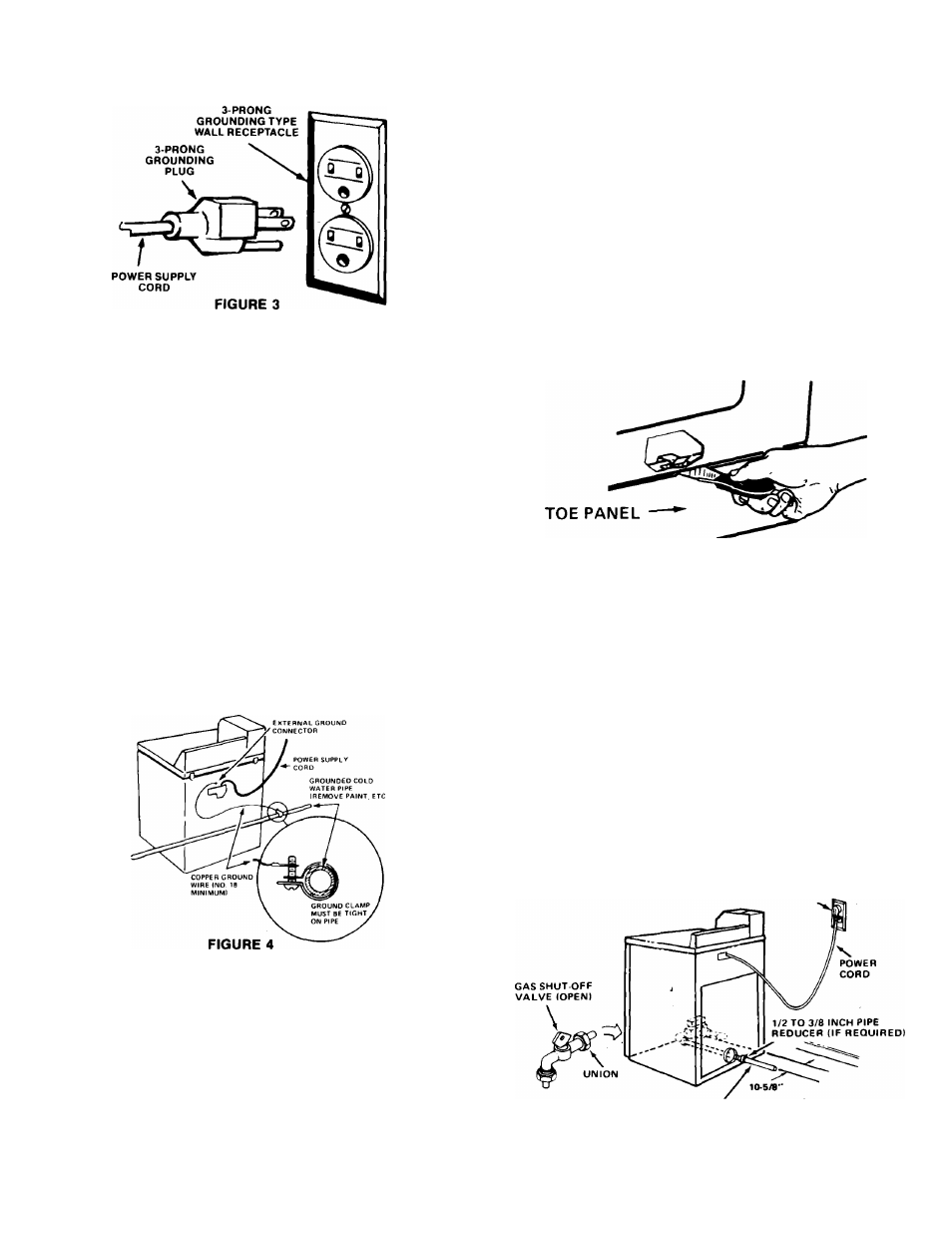
If this is done, you must connect a separate copper
ground wire (No. 18 minimum) to a grounded cold
water pipe* by means of a clamp and then to the
external ground connector screw. See Figure 4. Do
not ground to a gas supply pipe. Do not connect to
electrical supply until appliance is permanently
grounded.
•Grounded cold water pipe must have metal continuity to electrical
ground and not be interrupted by plastic, rubber or electrically
insulating connectors (including water meter or pump) without
adding a jumper wire at these connections.
INSTALLATION PROCEDURE
1. Open the dryer door and remove the shipping
tape that holds the d'rum to. the cabinet.
2. Remove all literature and installation parts
from the dryer drum.
3. Block up the front of the appliance about four
inches and install leveling feet in the front corners.
These feet should extend approximately one inch.
Remove the block and repeat the procedure at
rear of appliance.
4.
Refer to Exhaust System Requirements in these
instructions.
•'
5. Move the appliance to desired location. Observe
the minimum clearance to sides and rear as
specified on the label found on back panel of the
dryer.
To open the toe panel use a putty knife, press on
the toe panel lock located at the center top of the
toe panel. Pull downward on the toe panel to open.
The toe panel is hinged at the bottom. See figure 5.
FIGURE 5
6
.
Level the appliance from side to side and from
front to rear by adjusting the leveling feet. A small
spirit level placed on the dryer top is recommended
for leveling.
7. Connect the appliance to the gas supply. Make
sure the shut-off valve located behind the toe plate
is open (See Figure 6) and open shut-off valves in
the supply line. Test all gas connections for leaks,
using a brush and soapy water solution. (Liquid
detergent works very well also.) Bubbles will
indicate a loose connection.
NEVER TEST FOR GAS LEAKS WITH A FLAME.
120 VOLT 3-PRONG
RECEPTACLE (15 A(VIP)
1/2 INCH GAS PIPE 13/8 INCH APPROVED
COPPER TUBING MAY BE USED ON LP GASI
FIGURE 6