Warning, Electrical connection ^warning, Power supply cord – Whirlpool 3397612 User Manual
Page 3: Direct wire, K>wrat supply cord
Attention! The text in this document has been recognized automatically. To view the original document, you can use the "Original mode".
For use where
local codes
permit use of
flexible power
supply cord.
/
o
JJS
cm
A.
four-wire
receptacle(14-30R)
Figure 3
fhree-wire
receptacle(10-30R)
Figure 4
Four-wire connection...
POWER SUPPLY CORD
Four-wire installation is recommended
(required for mobile homes):
The power
supply cord must hove four. No,-10
copper wires and match a four-wire
recepfacle of NEMA Type 14-30R (see
Figure 3). The fourth wire (grounding
conductor) must be identified with a
green cover and the neutral conductor
by a white cover.
Three-wire installation (if a four-wire
system is not available):
The power
supply cord must have three, No.-lO
copper wires to match a three-wire
receptacle cf NEMA Type 10-30R (see
Figure 4).
Direct wire
The washer/dryer can be connected
directly to fused disconnect or circuit
breaker box with four-wire or fhree-wire
flexible armored or non-metallic
sheathed copper cable (with grounding
wire). Do Not use two-wire with bare
grounding wire. All current-carrying
wires must be insulated.
A conduit connector must be installed
at junction box. USE ONLY 10-GAUGE
SOLID COPPER WIRE. DO NOT USE
ALUMINUM WIRE. Allow four feet of slack
in the line so dryer can be moved if
servicing is ever necessary.
neufral (whife or
confer)
confer silvor-colorod
forminal block screw
power
supply cord
grounding
wire (green)
appliance
harness
rounding wire
(green wirh
yellow sfripes)
.exfernal
cabinef-
grounding
Infernal cabinef-.
grounding connector
conne
Figure 5
1. Disconnect the power supply.
2. Remove terminal block cover.
3. Install copper, four-wire power
supply cord through strain relief,
4. Remove the appliance harness
grounding wire (green with yellow
stripes) from the internal grounding
connector and fasten under
center, silver-colored terminal block
screw.
5. Connect the grounding wire
(green) of the copper, four-wire
power suppiy cord to the internal
grounding connector.
6. Connect the neutral wire (white) of
the power supply cord to the
center, silver-colored termindl screw
of the terminal block, Connect the
other wires to the outer terminals.
Tighten screws firmly.
7. Tighten strain relief screws.
8. Replace the terminal block cover.
ptor
Electrical connection
^WARNING
'if
Electrical Shock Hazard
Check that wiring you are using
matches colors shown in illustrations
and specified in instruction steps. If
wiring does Not match, it is your
responsibility to have a qualified
electrician install the correct wiring.
Failure to install the correct wiring
could result in death or serious injury.
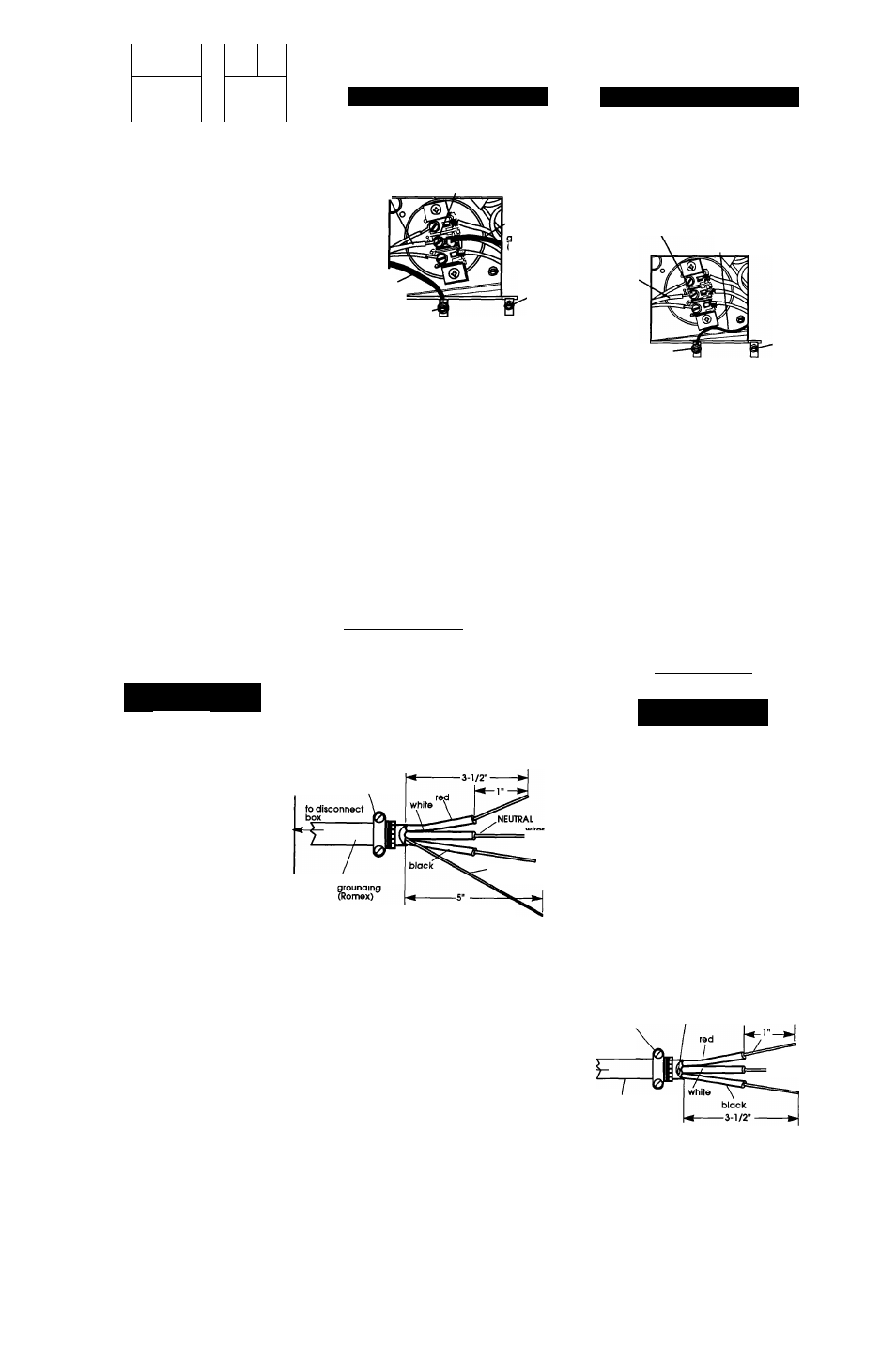
DIRECT WIRE
1. Disconnect the power supply.
2. Remove terminal block cover.
3. Strip 5 inches of oufer covering from
end of cable. Leave bare
grounding wire at 5 inches. Cut
1-1/2 inches from 3 remaining
insulated wires. Strip insulation back
1 inch (see Figure 6).
' U.L.-lisfed
sfrain relief
This washer/dryer Is manufactured with the
neutral terminal connected to the cabinet.
'Stripped
of
insulation
10-gauge, 3-wire
with ■■
wire
bare grounding
wire
Panel B
Direct wire preparation
Figure 6
r
U-shaped
hook
Figure 7
Shape the end of
each wire into a "U"
shaped hook (see
Figure 7). The bare
grounding wire must
be 4-1 /2" long after
forming the hook.
4. Install copper, four-wire power
supply cable through strain relief.
5. Remove the appliance harness
grounding wire (green with yellow
stripes) from the internal grounding
connector and fasten under center,
silver-colored terminal block screw.
6. Slide the hook end of the grounding
wire (bare) of the four-wire power
supply cable under the internal
grounding connector screw.
Squeeze hook end of wire together.
Tighten screw.
7. Connect the neutral wire (white) of
the power supply cable to the
center, silver-colored termindl screw
of the terminal block using the same
method. Connect the other wires to
the outer terminals. Tighten screws
firmly.
8. Tighten strain relief screws.
9. Replace the terminal block cover.
B.
Three-wire connection.
Where local codes permit
connecting cabinet-arounding
conductor to the neutral wire:
K>wrat SUPPLY CORD
cenfer silver-colored
terminal block screw
neutral
(white or
center)
Internal cabinet
grounding
connector
appliance harness
grounding wire
rareen with yellow
sfripes)
external
cabinet
grounding
connector
Figure 8
1. Disconnect the power supply.
2. Remove terminal block cover.
3. Install copper three-wire power
supply cord through strain relief.
4. Connect the neutral wire (white or
center) of the power supply cord to
the center, silver-colored terminal
screw of the terminal block.
Connect the other wires to the
outer terminals. Tighten screws
firmly.
5. Tighten sfrain relief screws.
6. Replace the terminal block cover.
Where local codes permit
connecting cabinet-arounding
conductor to the neutral wire of the
power supply cable:
DIRECT WIRE
1. Disconnect the power supply.
A
warning
Electrical Shock Hazard
Do Not use two-wire with a bare
grounding wire. All current-carrying
wires must be insulated.
Failure to install the correct wiring
could result in death or serious injury.
2. Remove terminal block cover.
3. Strip 3-1 /2 inches of outer covering
from end of cable. If using three-
wire cable with grounding wire, cut
the bare wire even with outer
covering. Strip 1 inch of insulation
from the end of each insulated wire
(see Figure 9).
3/4" U.L.-listed
strain relief
to
disconnect
box
Bare wire cut short. Wire is not
used. Dryer is grounded
through direct wire cable.
NEUTRAL
wires stripped
of Insulation
lO-gauge. 3-wire or,
10-gauge, 3-wire with
grounding wire (Romex)
r
Direct wire preparation
Figure 9
U-shaped
hook
Shape the end of
each wire into a
"U" shaped hook
(see Figure 10).
Figure 10