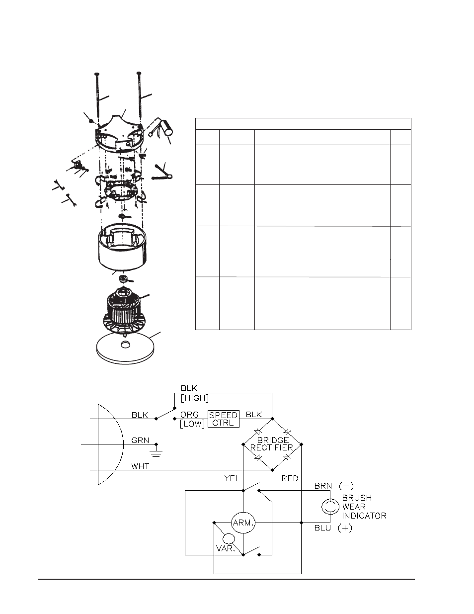
Motor assembly drawing, 120v motor schematic, Clarke – Clarke CFP-200 User Manual
Page 32
Page -32 -
Clarke
®
Operator's Manual
- CFP Polisher
Clarke
®
CFP-2000DS
Motor Assembly Drawing, Parts List and Schematic 7/05
Ref
Part No.
Description
Qty.
1
50717A
Thru-Bolt
2
2
N/A
Commutator Bracket
1
3
56282A
Hex Nut
1
4
912287
Rectifier, Bridge
1
5
962399
Screw, 8-32 x 1 1/4
1
6
448396
Spring (Included with #8)
(4)
7
51405A
Brush Asm., (Included w/#8)
(4)
8
51435A
Brush Board Asm. (incl #'s 6,7,16, 18,19) 1
9
962546
Screw, 10-24 x 1/2 Type 23
8
10
980608
#8 Flat Washer
1
11
58057A
Stator Frame
1
12
902550
Bearing-Ball- 6203 (Included w/#13)
(1)
13
40322A
Armature Asm. (Includes #12)
1
14
N/A
Strain Relief
1
15
N/A
Bushing
1
16
55648A
Red Lead (Included with #8)
(1)
17
980076
Wave Washer
1
18
55647A
Yellow Lead (Included with #8)
(1)
19
59606A
Varistor (Included w/#8)
(1)
20
46735A
Speed Control
1
21
53849A
Plate, Mounting
1
NI
80141A
Screw, 10-32 x 1
6
1
3
2
1
4
10
5
20
6
15
19
6
6
6
7
7
9
9
17
8
9
16
18
11
12
13
14
120V Motor
Schematic
MOTOR 40764A
21