Balancing, Radio installation, Battery installation – Carl Goldberg GBGA1024 User Manual
Page 9: Control set up, Control travel, Propeller
9
2.
*
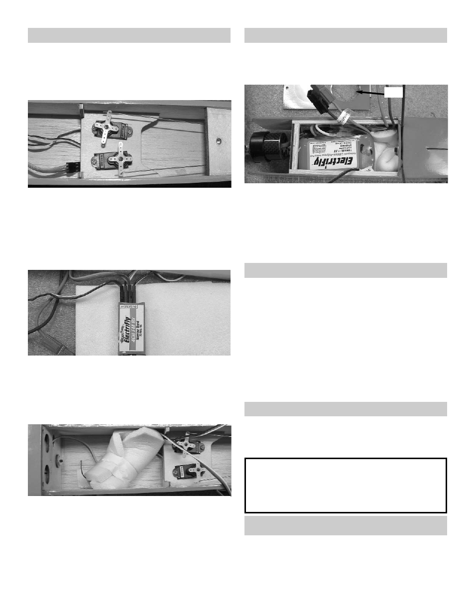
Mount the elevator and rudder servo as
shown above.
*
Attach the pushrods to the servo arms the
same way you did the aileron servos.
*
Mount the two servo arms to the top of the
servos.
Radio Installation
1.
*
Collect the following parts:
(1) Fuselage
(2) Micro Servos with Hardware (Not Included)
(1) Micro Receiver (Not Included)
(2) Servo “Y” Harness (Not Included)
3.
*
Plug the elevator and rudder servos into your
receiver.
*
Attach the “Y” harness to the receiver.
*
Plug in the speed control.
*
Cut foam and wrap around the receiver.
4.
*
Put the receiver wrapped in foam in front of
the servos.
*
Drill a hole for the receiver antenna wire in the
bottom of the fuselage.
*
Tape the receiver wire end to the bottom of the
fuselage at the tail.
1.
*
Collect the following parts:
(1) Fuselage
(1) 3 cell Li-Po Battery
Battery Installation
*
Insert foam into the front battery compart-
ment.
*
Slide the Li-Po battery into the front compart-
ment.
*
Cut a hole in the covering in the bottom hatch
to allow heat from the battery to escape.
Hole
Control Set Up
Turn on your transmitter and plug in the receiver
battery. Center all the control surfaces (rudder,
elevator & aileron). If required by your speed
control this is the time to program it for your
use.
Control Travel
Aileron
up / down 1” to 1-1/4”
Elevator
up / down 1/2” to 3/4”
Rudder
Right / Left 1”
Flap
Down 1” to 2”
Propeller
Install the prop adapter and your propeller at
this time. We used a 9 x 4.7 APC prop for our
motor, battery and speed control setup.
Caution:
The propeller can start turning any
time the receiver battery is plugged
in.
Balancing
Your model should balance 2-1/2” back from
the leading edge of the wing next to
the fuselage.