Disassembly & inspection – CAMCORP Blower Package with M-D Pneumatics Blower User Manual
Page 22
Disassembly of Blower
1. Remove unit from installation and drain lubricant from both ends by
removing magnetic drain plugs [31]. Mark end plates, covers and
housing so they can be reassembled in their original position.
2. Remove cap screws [26] from drive end cover [6]. Using a beveled
chisel and hammer, remove cover,
3. Remove cap screw [307 or 29], washer [27] and oil slinger [20]
4. Remove cap screw [62] and bearing retainer plates [14]. Note location
and sequence of wave springs [282] and spacers [281] as they are
removed.
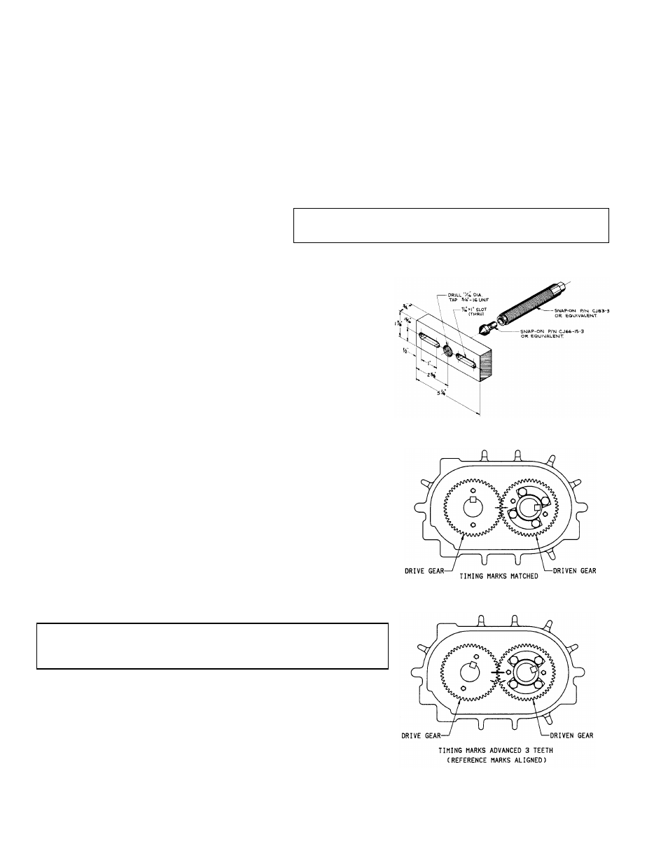
5. Attach bar pullers as shown in Figure 5 to each bearing bore and pull
end plate [4].
6. Remove cap screws [26] and gear end cover [7].
7. Remove gear lock bolts [29], and washers [25].
8. Align timing marks on gears (Figure 6A) Rotate drive gear clockwise
approximately three teeth and mark a matching reference line on each
gear as shown in Figure 6B. This gear position is necessary so rotors
will clear and not jam. Do not allow the gears to move from the
matched reference line while pulling. Use a light rocking motion to in-
sure that the lobes have not jammed. Remove driven gear first, and
then drive gear.
CAUTION: Failure to properly pull this gear could result in damage to
rotor keyway or a bent rotor shaft. Never use excessive
force.
9. Remove cap screws [62] and bearing retainer plates [14].
10. Using bar puller attached to bearing bore, push one rotor [1 & 2] at a
time from end plate. Keep rotor lobes in vertical position while remov-
ing.
11. Using a mallet, tap end plate from housing.
12. Tap out bearings [9 & 10] or [50], and seals [12 & 13].
13. Remove seal rings [58] from rotor shaft sleeves [239].
14. Inspect all parts for wear.
DISASSEMBLY & INSPECTION
With proper maintenance and lubrication, normal life expectancy for gears, bearings, and seals can be achieved. However,
over a period of time these parts must be repaired or replaced to maintain the efficiency of your blower. This section is
written in a way that will allow you to completely disassemble your blower. The inspection of certain repairable or
replaceable parts is referred to at the point of disassembly where these parts are exposed. If at any point of inspection,
repair or replacement is deemed necessary, appropriate instruction will be given to achieve these repair or replacement is
deemed necessary, appropriate instruction will be given to achieve these repairs or replacements.
Remove the oil drain plugs [18] in the bottom of the end covers [Items 5 & 10] and drain the oil. Take out eight cap screws
[16] and remove the gear cover. It may be necessary to tap the sides with a mallet or wooden block to break the seal joint.
Gears are not exposed for visual inspection. Items in brackets [ ] are referenced to item numbers on page 16, 18 or 20 as
applicable to the blower model.
Inspect the gears for the following:
•
Broken Teeth
•
Chipped Teeth
•
Uneven Wear
•
Excessive Wear
•
Any Other Abnormalities
WARNING:
Before performing any repair or replacement,
disconnect and lock out power.
10
Figure 5.
Figure 6A.
Figure 6B.