Installation & maintenance instructions, Asco valves, Pc-series – CAMCORP Blower Package with Sutorbilt Blower User Manual
Page 59: Description, Installation
Page 1 of 4
50-60 Hanover Road, Florham Park, New Jersey 07932
ASCO Valves
e
MCMXCI All Rights Reserved.
Installation & Maintenance Instructions
PC-SERIES
Form No.P7050R1
SWITCH UNITS
OPEN-FRAME TYPE, GENERAL PURPOSE, OR WATERTIGHT SWITCH ENCLOSURE
TWO-STAGE FIXED DEADBAND SWITCH UNITS
DESCRIPTION
The PC-Series Two-Stage Fixed Deadband Switch Units are used with
transducer units to make Tripoint Pressure Switches or Temperature
Switches. The switch units are made of aluminum alloy and designed for
rugged use. The switch unit may be provided as open-frame type or with a
general purpose or watertight enclosure. All wiring terminals, adjustments,
and visual scales are accessible from the front of the switch.
The switch may be supplied as a complete unit, with the switch unit and
transducer unit completely assembled. The components may be separate
units to be assembled upon installation. The two-stage switch unit has two
adjusting nuts which provide independent adjustment of the two electrical
switches. Each switch has an adjustable (set) point and non-adjustable
(reset) point. The difference between the set point and the reset point is the
fixed deadband. The actuation points of the electrical switches cannot be
identical but require a minimum separation. The switch assembly can be
mated with a wide selection of pressure and temperature transducers to cover
a broad range of pressure, fluids, and temperatures. The switch will control
electrical circuits in response to change in pressure and temperature signals.
IMPORTANT: These instructions cover the installation and use of this
switch on pressure and temperature transducers. Select the paragraphs that
apply to your particular installation and application. The word signal is used
in place of pressure or temperature changes.
INSTALLATION
Check the nameplate for the correct catalog number, pressure range,
temperature range, media, and proof pressure or rated overrange temperaĆ
ture. Never apply incompatible fluids or exceed the pressure or temperature
rating of the switch. Installation and inspection to be performed by qualified
personnel.
Nameplates are located on the switch (or switch cover) and on the bottom of
the transducer. Check to be sure the third digit in each number is the same.
If not, the unit should not be used (Refer to Figure 4).
IMPORTANT: All internal adjustments have been made at the factory. Any
adjustment, alteration or repair to the internal parts of the switch other than
stated herein voids all warranties. The signal setting adjustments required
are made by the adjusting two nuts on the top of the switch.
Temperature Limitations
Switch ambient temperature limits are -4_F (-20_C) to 122_F (50_C). To
determine fluid temperature limitations, see Form No. P7051 for pressure
transducer catalog numbers and construction materials, then refer to chart
below.
TRANSDUCER
CONSTRUCTION MATERIALS
RATINGS
FLUID TEMPERATURE
Buna N or Neoprene
-4
_
F (-20
_
C) to 180
_
F (82
_
C)
VITON*
-4
_
F (-20
_
C) to 250
_
F (121
_
C)
316 Stainless Steel
-50
_
F (-45
_
C) to 300
_
F(149
_
C)
All Nylon
Maximum 180
_
F (82
_
C)
All Nylon
For Water Service
Maximum 130
_
F (55
_
C)
For stream service, the fluid temperature with a pigtail (siphon tube or
condensate loop) installed directly into the transducer will be below 180_F
(82_C).
Assembly Of Switch And Transducer Units
(Refer to Figure 4)
IMPORTANT: The switch unit and transducer unit may be purchased as a
complete assembly or as separate units. If separate units are purchased,
refer to Form No. P7051 for a complete listing of switch unit and transducer
unit combinations. Form No. P7051 is provided to ensure that the proper
switch unit is assembled to the proper transducer unit.
Pay careful attention to exploded view provided in Figure 4 for assembly of
switch unit and transducer unit. Proceed in the following manner:
CAUTION: The third digit in the catalog number on both the switch unit and
the transducer unit must be identical. If not, do not assemble to each other.
If the same, proceed.
1. Remove bolts (4) from base of switch unit. On general purpose or
raintight constructions, remove switch cover.
2. Remove instruction label and pressure or temperature switch range
scale from the transducer unit.
3. Place transducer unit on base of switch unit and assemble. Start bolts
(4) approximately two turns by hand to avoid the possibility of cross
threading. After initial engagement, torque bolts (4) in a crisscross
manner to 80±10 in-lbs [9,0± 1,1 Nm].
4. Remove backing paper from range scale and install on the front of the
switch body over the opening for the adjusting indicator point.
Positioning
Switch may be mounted in any position.
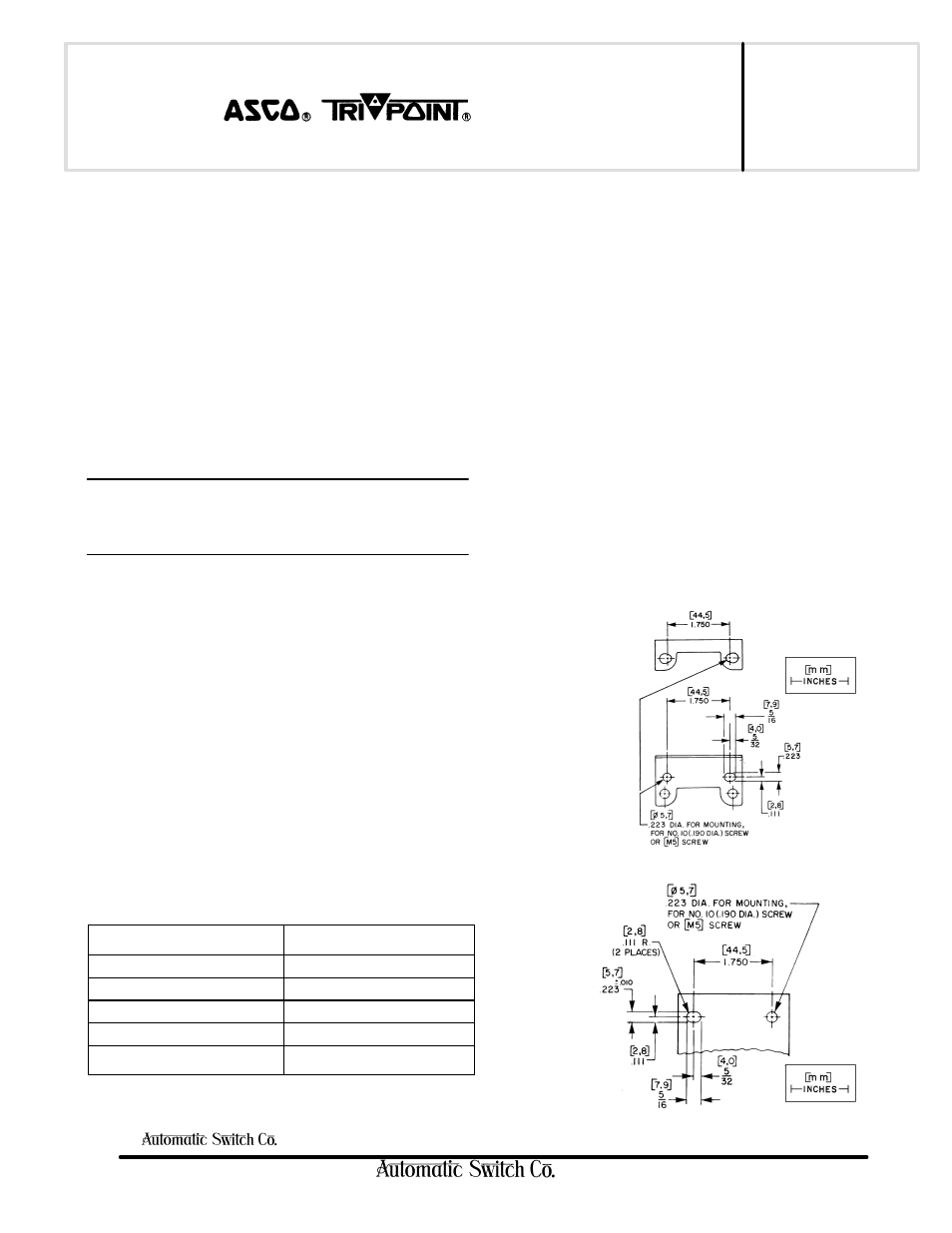
Mounting
Refer to Figures 1 and 2 for mounting.
Figure 2. General Purpose Enclosure
Figure 1. Optional Mounting Bracket