CAMCORP Blower Package with Sutorbilt Blower User Manual
Page 47
SB-7-621 Page 34
16. Replace drive shaft grease seal (31) in the drive end cover (29). The seal lip should always face towards the
bearing or lubricant. Pack bearing cavities with recommended grease and secure drive cover with capscrews
(30) to drive headplate. Refer to FIGURE 7-8 for torque specifications.
Exercise care not to damage the seal lip as it passes over the shaft keyway.
17. Assemble the gear cover (3) and gasket (7) to the gear headplate (18) using capscrews (5). Tighten the
capscrews alternately and evenly. Refer to FIGURE 7-8 for torque specifications.
18. Place the blower on its feet on a flat surface. Loosen cap screws (16) and level the unit up. The bench or
blower base flatness should be within .002 of an inch. Re--tighten cap screws (16) to the specification in
FIGURE 7-8.
NOTICE
If the unit is not flat within .002 of an inch, it will be necessary to shim the blower feet at installation.
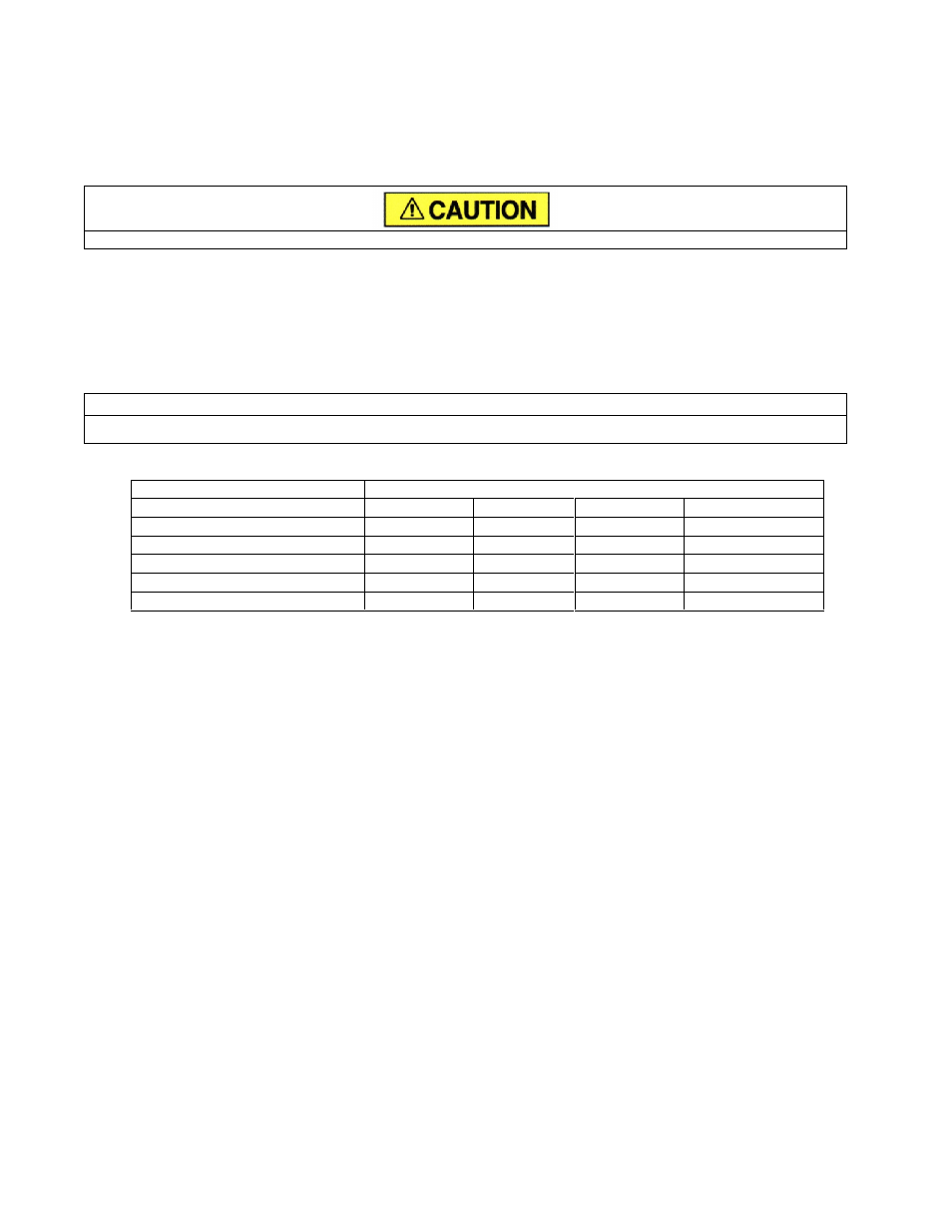
GEAR DIAMETER
FASTENERS
2
3
4
5
CAPSCREW (21)
13 – 17
23 – 30
23 – 30
23 -- 30
CAPSCREW (16)
13 – 17
23 – 30
23 – 30
23 -- 30
SOCKET HD CAPSCREW (5)
6 – 8
6 – 8
13 – 17
13 -- 17
SOCKET HD CAPSCREW (30)
6 – 8
6 – 8
13 – 17
6 -- 8
CAPSCREW (10)
6 – 8
6 – 8
13 – 17
13 -- 17
NOTE: ( ) DENOTES ITEMS IN EXPLODED VIEW DRAWINGS ON PAGES 35, 37, 39 AND 41.
FIGURE 7-8 – TORQUE (FT-LBS)