C&D Technologies 41-7525 VRLA Batteries (rack mounted systems) User Manual
Page 3
12V VRLA BATTERY SYSTEM
OPEN RACK INSTALLATION AND
SYSTEM CHECKOUT GUIDE
General Information
This document provides a guide for use during
receiving, installation and checkout of the 12V
VRLA batteries of 25 through 200 ampere-hours
capacity on open rack systems.
This guide may not be complete within itself
and should be used in conjunction with the
following:
1. Rack Installation Drawing (M16285)
2. Specification Sheet for individual battery
3. Self Discharge and Inventory Control
technical bulletin #41-7272
4. Integrity Testing technical bulletin #41-7264
5. Operational Qualification and Warranty
Registration Checklist technical bulletin
#41-7471
Other related C&D Technologies pamphlets
which may be of interest include:
1. Impedance and Conductance Testing
technical bulletin #41-7271
2. Acceptance and Capacity Testing
technical bulletin #41-7135
3. UPS Applications and VRLA Battery Sizing
technical bulletin #41-7334
4. Communications Applications and VRLA
Battery Sizing technical bulletin #41-7361
C&D Technologies 12V VRLA Battery
System General Description
The 12V valve regulated lead acid (VRLA)
battery is a lead acid battery which facilitates
the recombination of internally generated
gasses. As a result the battery vents minimal
gas during normal conditions and does not
require the addition of water to the electrolyte.
The electrolyte is either in a gelled form or is
absorbed in the blotter type of separator thus
eliminating any free liquid electrolyte. Each cell
within the battery contains a self resealing
pressure relief vent to relieve any excess
pressure generated during overcharge and the
battery is otherwise essentially sealed.
The typical 12V battery system is a group of the 6
or 12 VDC individual batteries connected in series
to provide a higher voltage and power to a critical
load during commercial power outages. Typical
system voltages are in the range of 12 through
480 VDC depending on the application. For
example 12, 24 and 48 VDC might be used for
communications equipment standby power while
from 72 to 480 VDC might be used for data center
UPS systems.
The lead acid battery has a nominal voltage of 2
VDC per cell. A 6 volt battery has 3 cells. Just as
the voltage of a battery system is increased by
connecting the individual multicell blocks in series,
the ampere-hours and kilowatt capacity of the
systems can be increased by connecting strings of
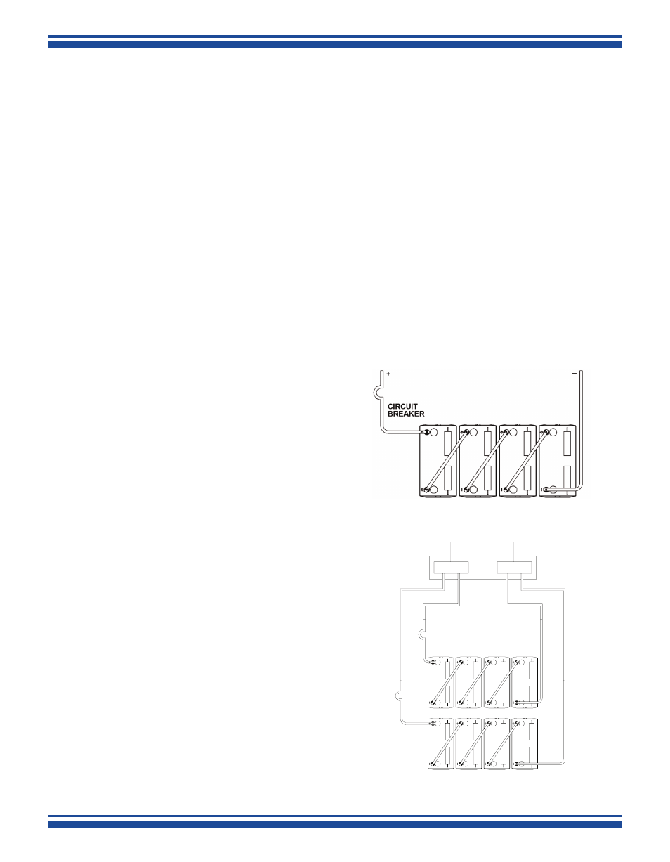
series connected batteries, in parallel. Refer to
Figures 1 and 2 for examples of series and parallel
connected batteries.
41-7525/0514/CD 3 www.cdtechno.com
JUNCTION
BOX
+
_
L1
L3
L2
L4
STRING B
STRING
A
CIRCUIT
BREAKER B
CIRCUIT
BREAKER A
NOTE: L1 + L2 = L3 + L4
Figure 1-Series Connected Batteries
Figure 2-Two Strings of Batteries
Connected in Parallel