Pto shaft modification (for heavy duty mowers) – Behlen 80110060YEL User Manual
Page 7
PTO SHAFT MODIFICATION
(For Heavy Duty Mowers)
Read and thoroughly understand the
following instructions before
attempting assembly. If you are not
comfortable making the necessary
changes, please refer this project to a
qualified professional.
WARNING: Never stand between
tractor and Rotary Cut Mower when
backing up the tractor to the hitch.
Attach unit to the tractor's Category 1 3-Point
hitch as described in the tractor's Operating
Manual.
NOTE: Due to the many variations in tractor hitch
points and distances between equipment
gearbox input shaft and tractor PTO output
shafts, some combinations will require PTO
shafts to be shortened. If it is determined that this
is the case, follow the instructions in the next
steps.
1. Raise and lower the Mower in order to locate
the shortest distance between gearbox input
shaft and tractor PTO output shaft. With the
Mower in the shortest distance position, shut
down the tractor and securely block the
mower in place. See Blocking Requirements.
If the Mower is raised up so that the PTO shaft
is an an angle sharper than 35 degrees, PTO
MUST BE STOPPED!
2. Pull apart the PTO shaft and attach outer
section to tractor PTO shaft. NOTE: Be sure
to pull on PTO shaft section to ensure yoke
has locked into place.
3. Place and hold inner PTO shaft section next
to outer section and check if PTO shaft is
too long. Each section should end
approximately 3" short of reaching the
U-joint shield on the opposite section. If
the shaft is too long, measure 3" back from
each U-joint shield and mark the other shaft
section. Be sure to do this for both PTO
shaft halves. NOTE: Do not cut PTO shaft
sections at this time.
4. Raise Mower and remove blocking. Raise
and lower Mower in order to locate the
longest distance between equipment input
shaft and the tractor PTO output shaft. With
the Mower in the longest distance position,
shut down the tractor and securely block
the Mower in place.
5. As in Step 3, hold PTO shaft sections
together and check for a minimum of 6" of
overlap. If the PTO shaft has been marked
for cutting, the overlap is the distance
between the two marks. If the PTO shaft
has less than 6" of overlap, DO NOT USE.
Contact your authorized dealer.
NOTE: If the PTO shaft is too long, see
further instructions below for sizing.
6. Apply multi-purpose grease to the outside
of the male (inner) PTO shaft section.
Assemble PTO shaft and install on Mower
and tractor.
7. Pull on tractor side of PTO shaft yoke to be
sure it has locked in place. Make certain
PTO shaft shielding is in place and good
working condition.
8. The PTO shaft shield is a non-rotating
design and must be secured prior to use.
Using the chain on each yoke shield, attach
to a fixed object on the tractor and
equipment ends so that the PTO shaft
shield will not rotate during operation.
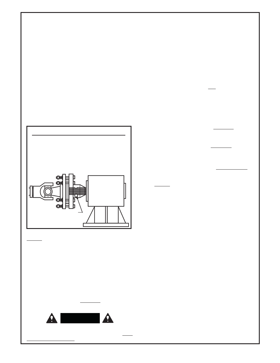
To install PTO shaft with Slip Clutch
1) Remove bolt as shown.
2) Attach PTO shaft.
3) Line up hole and groove in shaft.
4) Replace bolt and tighten.
BOLT
WARNING
F-20855
1-12-11