Wiring diagram (continued), Switch indication, Operation – Panasonic FV-13VKML3 User Manual
Page 6: Operation -7
Attention! The text in this document has been recognized automatically. To view the original document, you can use the "Original mode".
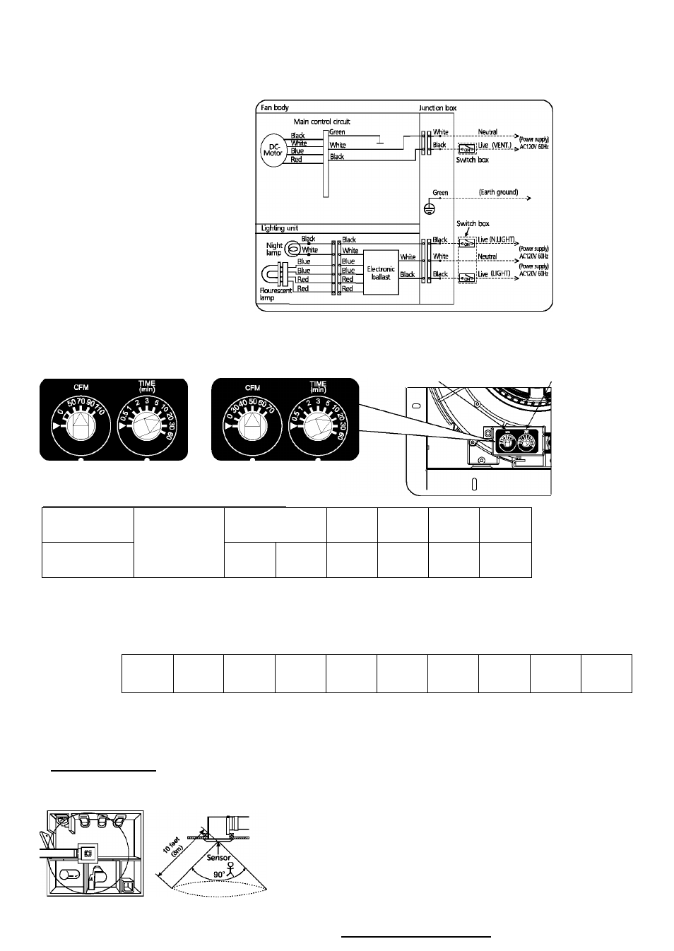
WIRING DIAGRAM (CONTINUED)
FV-13VKL3 FV-08VKL3
SWITCH INDICATION
FV-13VKML3
FV-13VKSL3
FV-08VKML3
FV-08VKSL3
Low speed air volume
preset switch
Switch indications
Switch indications
on blower unit
on blower unit
Low speed air-volume preset switch positions
High/Low delay time
preset switch
FV-13VKML3
FV-13VKSL3
Air volume
[CFM]
0
50
70
90
110
FV-08VKML3
FV-08VKSL3
0
30
40
50
60
70
Factory setting : FV-13VKML3/FV-13VKSL3: 70CFM;
FV-08VKML3/FV-08VKSL3: 50CFM.
Position
"
0
"
: Fan stop.
Position " ►" : use for factory test only.
High/Low delay time preset switch positions
►
0.5
1
2
3
5
10
20
30
60
Delay Time
[min]
Factory setting : 20 minutes.
Position : use for factory test only.
(Models of FV-13VKL3 and FV-08VKL3 have only one steady air volume.)
OPERATION____________________________
■ Sensor detectible range (For models of FV-13VKML3 and FV-08VKML3 only)
The distance that motion
can be detected is iimited
to 10 feet (3 m).
The fieid of view of the
sensor is 90°.
(Room temperature is
25”C)