Vi. plc input/output configuration table – Kistler-Morse KM SVS2000 User Manual
Page 11
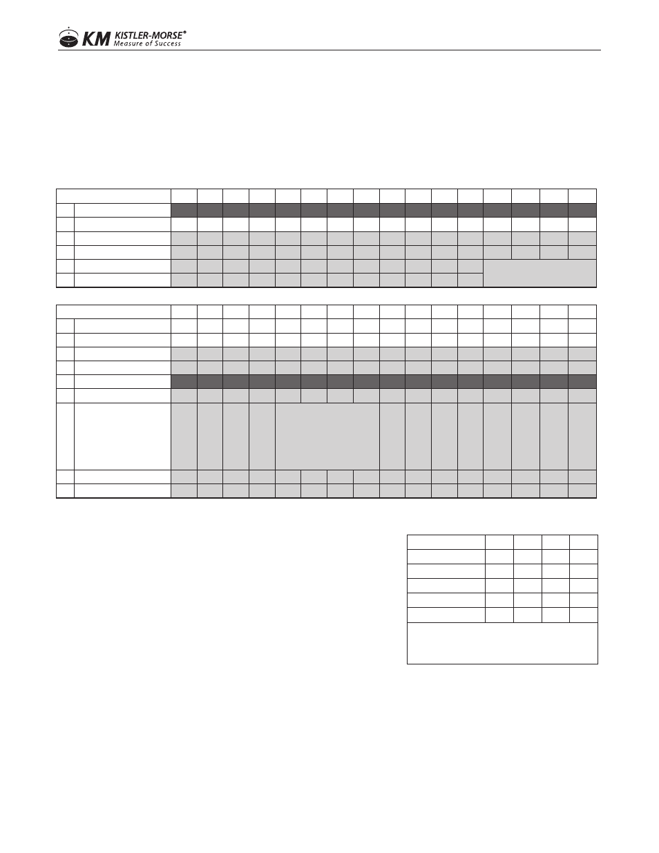
OUTPUT WORD
WORD
16
15
14
13
12
11
10
9
8
7
6
5
4
3
2
1
1
Tare MSW
2
Tare LSW
CH4*
CH3*
CH2*
CH1
3
Read/Write
WR
RD
4
Variable ID
5
Variable Write MSW
* Channels 2-4 only available
on Weigh II
6
Variable Write LSW
INPUT WORD
WORD
16
15
14
13
12
11
10
9
8
7
6
5
4
3
2
1
1
Gross MSW
2
Gross LSW
3
Net MSW
4
Net LSW
5
Status MSW
6
Status LSW
Not Used
Not Used
Not Used
Not Used
FORMAT BITS
Gr
oss Units Negative
Gr
oss/Net Unit
Err
or
ADC Err
or
Comm Err
or
A
vg or
C
al
ib
ra
tio
n
Er
ro
r
Move Mor
e
Material
Not Used
Net Units Negative
7
Variable Read MSW
8
Variable Read LSW
VI. PLC INPUT/OUTPUT CONFIGURATION TABLE
FORMAT BITS
12
11
10
9
XXXXXX
0
0
0
0
XXXXXX00
0
0
0
1
XXXXXX00
0
0
1
0
XXXXX.X
0
1
0
0
XXXX.XX
0
1
0
1
XXX.XXX
0
1
1
0
* Channels 2-4 only available
on Weigh II
At this point weight data and status should be received by the PLC. The PLC should be able to set the required tare
command bit in order to force the SVS2000 to tare and read/write a supported variable. Currently there are only two (2)
supported variables that can be read/written.
Read/write is optional and not required for gross/net values.
• TO READ A VARIABLE:
a. In the Output Word, set Read/Write bit (line 3) to
000000000000001
b. In the Output Word, set the Variable ID (line 4) to
000000000000001 for Setpoint 1 or 0000000000000010
for Setpoint 2. Subsequently, the value will be returned in
the Input Word, Variable Read (line 8).
• TO WRITE A VARIABLE:
a. In the Output Word, set Read/Write bit (line 3) to
000000000000010
b. In the Output Word, set the Variable ID (line 4) to 000000000000001 for Setpoint 1 or 0000000000000010
for Setpoint 2.
c. Add the new input values, in binary, to the Output Word, Variable Write (line 6 or 5 and 6). What is
written in line 6 or 5 and 6 will show up on the Input Word in lines 8 or 7 and 8. Invalid values will be
ignored.
7
www.kistlermorse.com
97-1501-12 Rev. B