8 | technical data – GEA Bock HG44e User Manual
Page 29
D
GB
F
E
29
96280-12.2014-DGbFEIRu
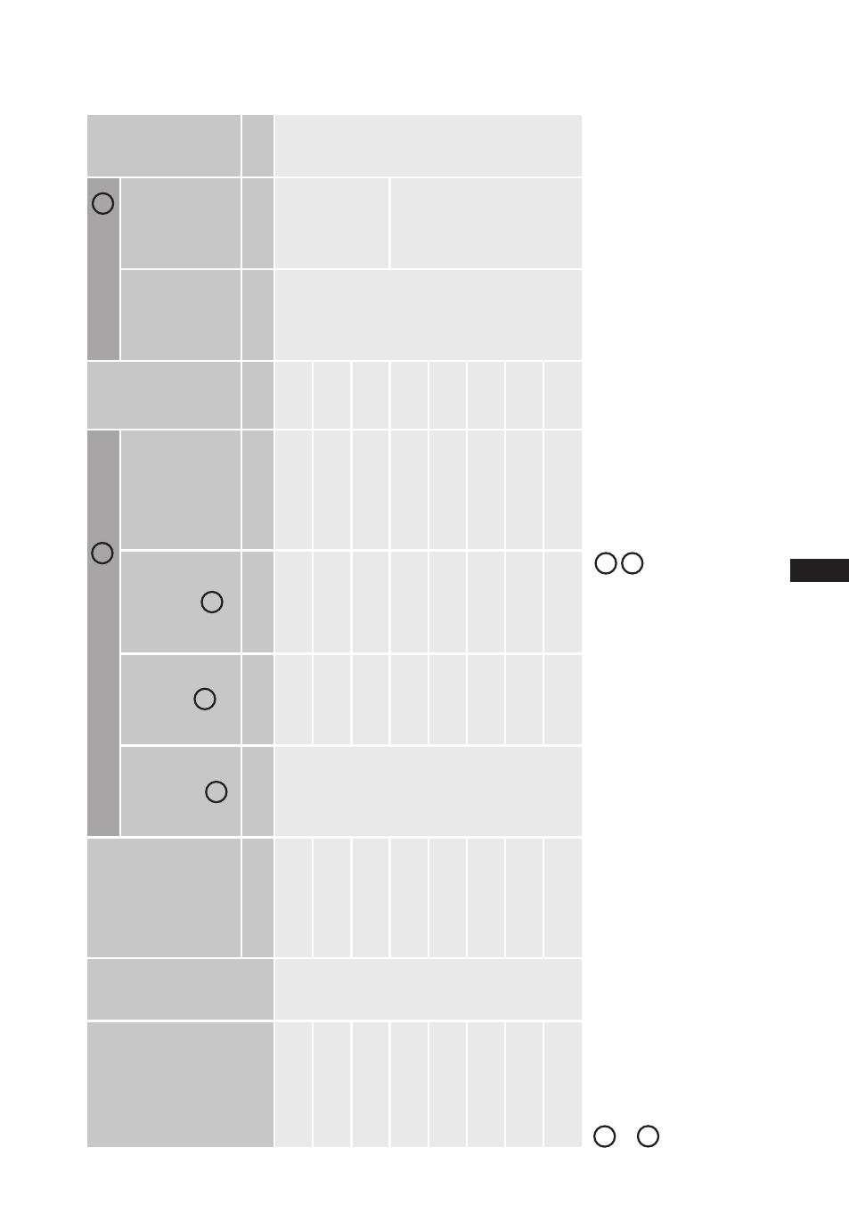
8 | Technical data
Ty
pe
No. of cylinders
Displacement
50 / 6
0 H
z
(1
45
0
/ 1
74
0
rpm
)
Ele
ct
ri
ca
l d
at
a
W
ei
gh
t
Conn
ec
tion
s
Oil charge
Vo
lta
ge
Ma
x.
Op
er
at
in
g
cur
re
nt
PW 1 + 2
M
ax
.
po
w
er
co
n-
sum
pt
ion
St
ar
tin
g
cur
re
nt
(r
ot
or
loc
ke
d)
PW 1 / P
W 1 + 2
Dis
ch
ar
ge
lin
e
DV
Su
ct
ion
lin
e
SV
m
3
/h
A
kW
A
kg
m
m
(in
ch
)
m
m
(in
ch
)
Lt
r.
HG4
4e
/4
75
-4
4
41
,3 / 4
9,
6
19
11
,0
83 / 1
09
16
4
28 / 1
1
/
8
35 / 1
3
/
8
2,
3
HG
44
e/
475
-4 S
41
,3 / 4
9,
6
23
13,1
115
/ 15
0
168
HG4
4e
/5
65
-4
49
,2 / 5
9,
0
22
13,2
83 / 1
09
164
HG4
4e
/5
65
-4
S
49
,2 / 5
9,
0
26
15,6
13
3 / 1
71
170
42 / 1
5
/
8
HG4
4e
/6
65
-4
57
,7 / 6
9,
2
26
15,4
115
/ 15
0
171
HG4
4e
/6
65
-4
S
57
,7 / 6
9,
2
30
18,3
13
3 / 1
71
168
HG4
4e
/7
70
-4
67
,0 / 8
0,4
30
17,8
13
3 / 1
71
168
HG4
4e
/7
70
-4
S
67
,0 / 8
0,4
35
21,4
13
3 / 1
71
168
1
2
3
2
4
380-420 V Y/YY - 3 - 50 Hz PW
440-480 V Y/YY - 3 - 60 Hz PW
PW = Part Winding
Winding ratio
: 70% / 30%
Tolerance
(±
10%)
rela
tive
to
the
mean
value
of
the
volta
ge
range.
Other
volta
ges
and
types
of
current
on
request.
-
Th
e
sp
ec
ifi
ca
tio
ns
fo
r ma
x.
p
ow
er
c
on
su
m
pt
io
n
ap
pl
y
fo
r 5
0H
z
op
er
at
io
n.
Fo
r 6
0H
z
op
er
at
io
n,
th
e
sp
ec
ifi
ca
tio
ns
h
av
e
to
b
e
m
ul
tip
lie
d
by
th
e
fa
ct
or
1
.2
.
Th
e ma
x. w
or
kin
g c
ur
re
nt r
ema
in
s u
nc
ha
ng
ed
.
-
Take account of the max.
opera
ting current / max.
po
wer consumption for
design of fuses,
supply lines and safety devices.
Fuse:
Consumption ca
tegor
y
AC3
1
2
All
specifica
tions
are
based
on
the
a
vera
ge
of
the
volta
ge
range
For solder connections
3
4