4 | compressor assembly – GEA Bock HG44e User Manual
Page 13
D
GB
F
E
13
96280-12.2014-DGbFEIRu
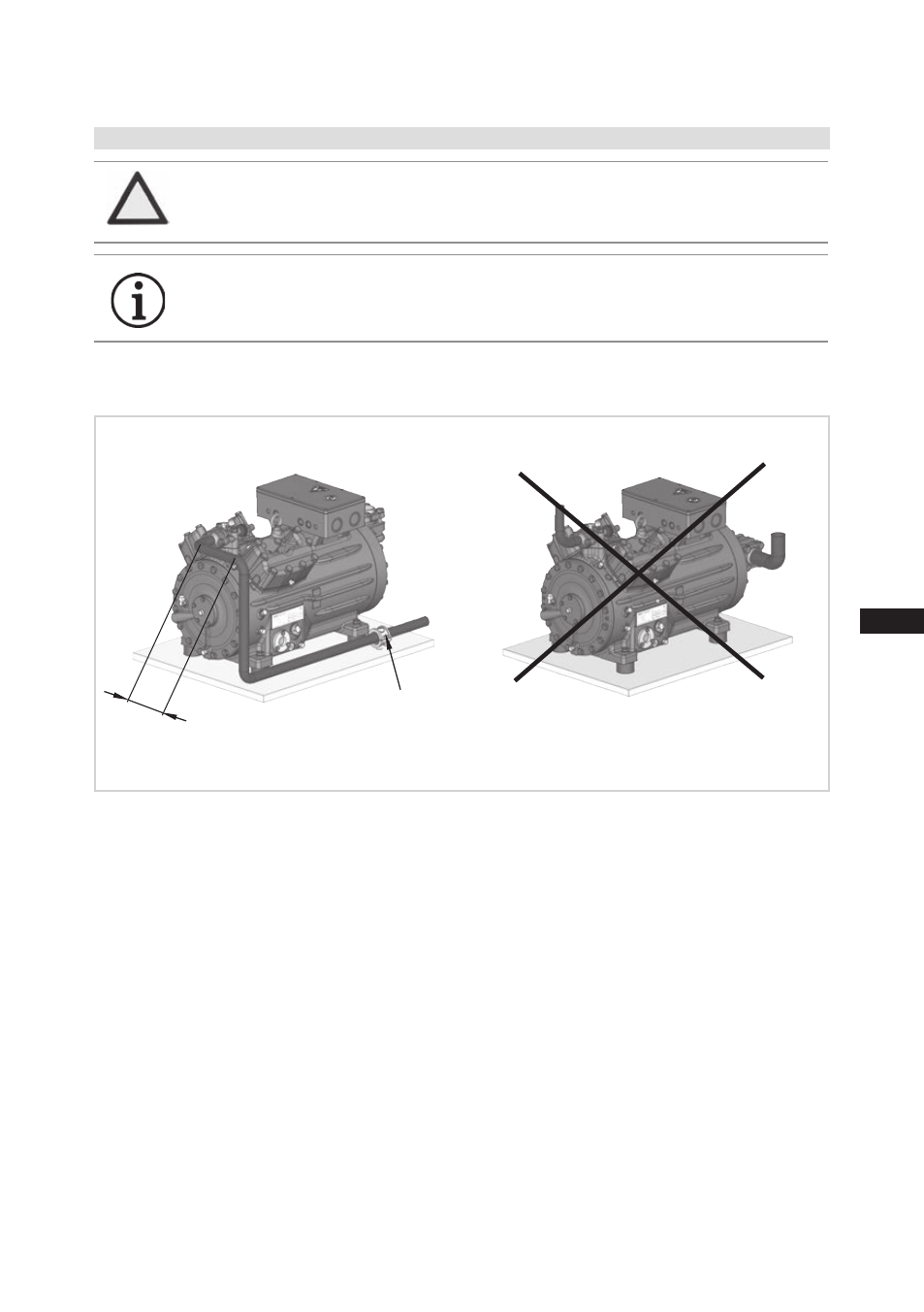
4.5 Laying suction and pressure lines
4 | Compressor assembly
Fig. 16
As short as
possible
Rigid
fixed point
1
2
3
4
5
6
7
8
9
10
11
12
13
A rule of thumb: Always lay the first pipe section starting from the shut-off valve downwards and
parallel to the drive shaft.
ATTENTION Improperly installed pipes can cause cracks and tears, the result
being a loss of refrigerant.
INFO
Proper layout of the suction and discharge lines directly after
the compressor is integral to the system’s smooth running and
vibration behaviour.
See also other documents in the category GEA Bock Air equipment:
- HG5 (32 pages)
- HG7 (34 pages)
- HG4 (32 pages)
- HG6 (32 pages)
- HG8 (38 pages)
- HG34e (30 pages)
- HG22Р (26 pages)
- HG12Р (26 pages)
- BCM2000 (18 pages)
- HG22e (26 pages)
- HG34P (26 pages)
- HG88e (38 pages)
- HА4 (32 pages)
- HА34P (26 pages)
- HA12P (26 pages)
- HA5 (32 pages)
- HA6 (32 pages)
- HG22Р CO2 (28 pages)
- HG34P CO2 (28 pages)
- HG4 CO2 (30 pages)
- HG12Р CO2 (28 pages)
- HG12e CO2 (28 pages)
- HGX2 CO2 T (28 pages)
- HGX34 CO2 T (40 pages)
- HGX46 CO2 T (40 pages)
- HAX2 CO2 T (28 pages)
- HG5 R134a (32 pages)
- HG6 R134a (32 pages)
- HG7 R134a (32 pages)
- HG4 R134a (32 pages)
- HGZ7 (42 pages)
- F (44 pages)
- F18 (28 pages)
- FK40 (26 pages)
- FK30 (26 pages)
- FK50 (26 pages)
- FK20 (26 pages)
- HG22P A (28 pages)
- HG34e A (28 pages)
- HG22e A (28 pages)
- HGX34P 2 pole (32 pages)