Cub Cadet T65 Series User Manual
Page 76
T65 Series Vertical Shaft Engines
70
•
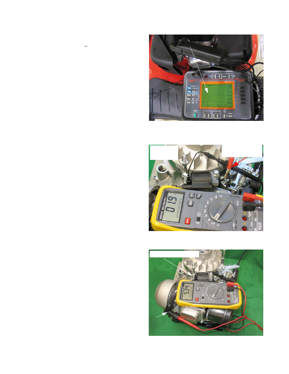
At pull-over speed (~ 600 RPM), voltage should
be at least 10,000V. See Figure 7.8.
NOTE: Flash-over voltage will vary with spark plug
condition and gap.
NOTE: Pull-over speed may vary from operator to
operator.
To measure the resistance of the module’s windings:
1.
Set a Digital Multi-Meter (DMM) to read resistance.
2.
Connect the one lead to the module’s laminations.
3.
Disconnect the Stop Switch.
4.
Connect the other lead of the DMM to the wire from
the module that was disconnected from the Stop
Switch. See Figure 7.9.
5.
Resistance in the primary windings of the ignition
module, measured between the spade terminal and
the laminations.
NOTE: The reading should be in the 1.0 - 2.0
range.
6.
Move the probe from the wire to the Stop Switch to
the spark plug wire. See Figure 7.10.
NOTE: The reading should be in the 5 K - 7 K
range.
•
There may be slight variation in specification
due to production variation and other factors
such as temperature.
•
Resistance figures that are vastly lower may
indicate a short in the windings being tested.
•
Resistance figures that are vastly higher (or
OL) may indicate a fault in the windings being
tested.
Figure 7.8
Pull-over speed: waveform is half-way
between 2nd and 3rd reticle (10,000 V.)
Figure 7.9
Probe to
laminations
Probe to wire to
stop switch
Figure 7.10
Probe to spark
plug terminal
Probe to laminations