Cub Cadet ogst3305 User Manual
Page 14
NOTE: See Ad just ment sec tion for
"Au ger Belt Ad just ment".
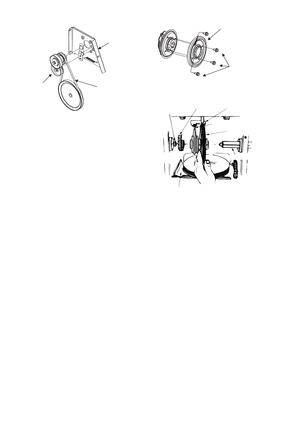
To Remove the Drive Belt:
a. Pull idler pul ley away from belt. See
Fig ure 19.
b. Re
move drive belt from the en
gine
pul ley and bot tom drive pul ley.
c. Re place belt and re as sem ble in re -
verse or der.
•
Re as
sem ble the two halves of the unit
hook ing the lower por tion of the au ger
hous
ing over the sta
tion
ary shoul
der
bolts in the frame as sem bly.
•
Se
cure the two halves with the two
screws and lockwashers.
•
At
tach the “Z” fit
ting of the ca
ble into
the brake bracket as sem bly. See Fig ure
16.
•
Slip the au
ger drive belt over en
gine
pul ley.
•
In
sert fer
rule on au
ger idler rod into
bracket bracket as sem bly and se cure with
flat washer and cot ter pin.
•
Re
as
sem
ble the large shoul
der bolt and
lockwasher as shown in Fig ure 15.
•
Re as sem ble belt cover, chute as sem bly
and chute crank.
Changing the Friction Wheel
The rub ber on the fric tion wheel is sub -
ject to wear and should be checked
af ter 25 hours of op er a tion, and pe ri od i -
cally there
af
ter. Re
place the fric
tion
wheel rub
ber if any signs of wear or
crack ing are found.
•
Drain the gas
o
line fr om the
snowthrower, or place a piece of plas tic
un der the gas cap.
•
Tip the snowthrower up and for ward, so
that it rests on the hous ing.
•
Re
move six self-tap
ping screws from
the frame cover un
der
neath the
snowthrower and re move cover.
•
Re move the wheels from the axle.
•
Using a 7/8" wrench hold the hex shaft
and re
move the hex bolt and cupped
washer and bear ing from left side of the
frame. See Fig ure 10. Hold the fric tion
wheel as sem bly, and slide the hex shaft
out of the unit to
ward the right hand
side.
•
Re
move the four screws from the fric
-
tion wheel as
sem
bly and re
move the
bonded fric tion wheel.
•
Re as sem ble new bonded fric tion wheel
rub
ber to the fric
tion wheel as
sem
bly,
turn each screw ap
prox
i
mately 2 turns
in or der shown in Figure 20 un til screws
are tight. It is im por tant for the rub ber
to be as sem bled sym met ri cally.
14
FIG URE 21
Shift Rod
As sem bly
Sprocket
Spacer
Sup port Bracket
Shaft
Fric tion
Wheel
Pin
FIG URE 19
Belt Cover
Support
Bracket
Drive
Belt
Idler
Pulley
1
2
3
4
FIG URE 20
Bonded fric tion
wheel rub ber
Hex
self-tap ping
screws