Warning – Cub Cadet GT-2544 User Manual
Page 40
40
6.
If not already done, pull the deck support pins
outward, turn downward and relesase so both
spring-loaded pins are held in the disengaged
position against the outer surface of the deck
brackets (See Figure 47).
Figure 47
7.
Carefully guide the tractor implement lift links (left
and right) into the rear deck bracket slots (left and
right) as the tractor implement lift handle is
lowered to its lowest setting (Refer to Figure 54).
8.
Pull both deck support pins outward and rotate rear-
ward to disengage the outer surface ot the rear deck
brackets. Release the pins, making certain each
deck support pin passes through the inner hole of
the rear deck bracket. The spring tension will push
the pins inward and, if aligned, through the hole in
each implement lift link (See Figure 48).
Figure 48
NOTE
It may be necessary to lift each side of the deck
and maneuver it slightly to align the support
pins with the holes of the lift links. Make certain
the support pins are fully extended through the
lift links to prevent the mower deck from
disengaging the lift links while mowing.
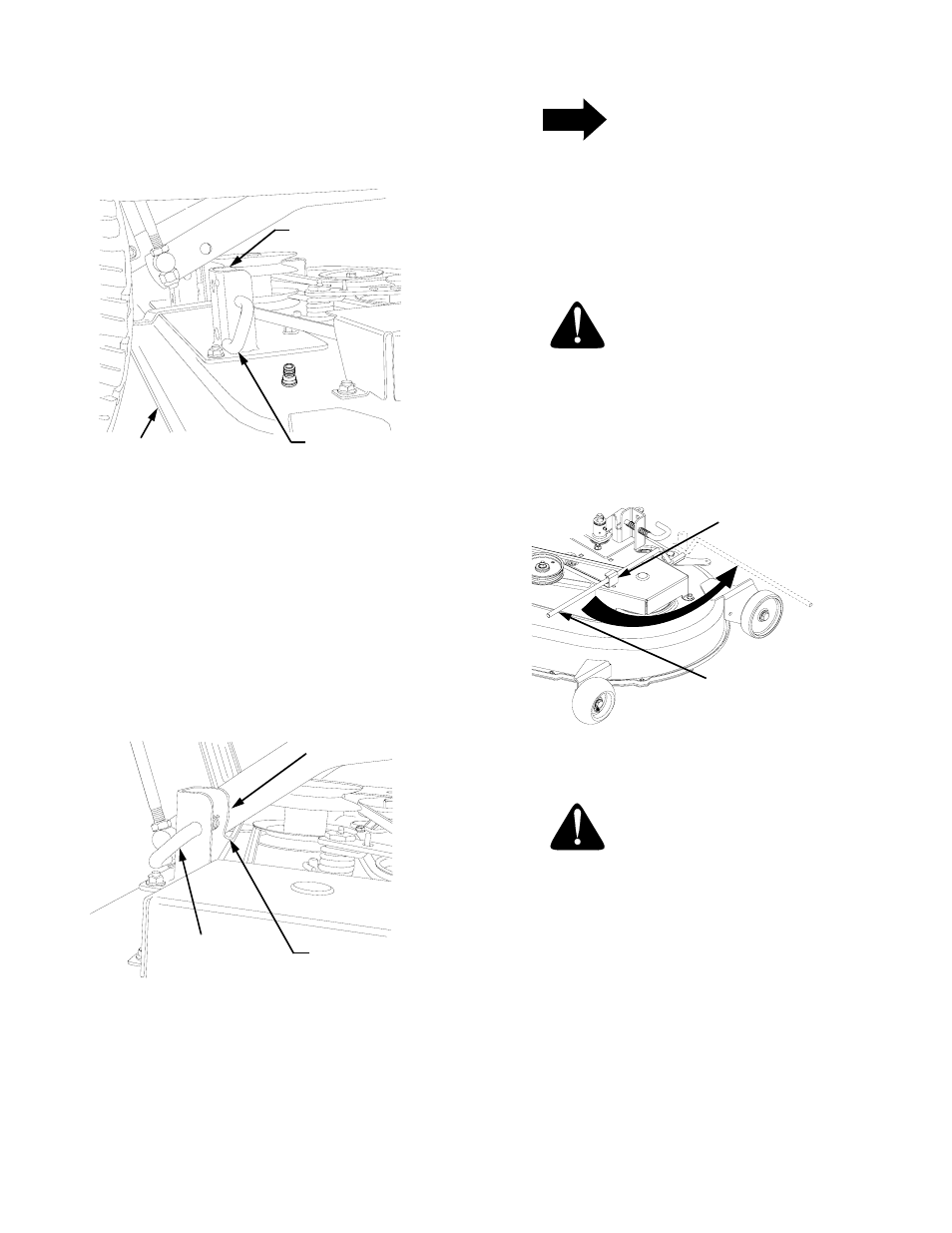
WARNING
The deck idler arm lever is spring loaded.
Release it slowly.
9.
Disengage the deck idler arm lever from its stop
bracket and release the spring tension by rotating
the lever out and rearward (See Figure 49).
Figure 49
WARNING
The exhaust system is HOT. To avoid personal
injury, allow the engine and exhaust system to
cool before proceeding with the following PTO
belt installation instructions.
REAR DECK
BRACKET SLOTS
DECK SUPPORT
PIN DISENGAGED
DECK
LIFT LINK HOLE
(BOTH SIDES)
SLOT IN REAR
DECK BRACKET
DECK SUPPORT
PIN ENGAGED
IDLER ARM
LEVER
LEVER STOP
BRACKET