Warning – Cub Cadet GT-2544 User Manual
Page 33
33
SECTION V. MOWER DECK
This section contains adjustment, removal, installation,
and maintenance information for the 44-inch mower
deck. Instructions for installation and removal of the
optional mulching plug are located at the end of this
section.
A. DECK LEVELING ADJUSTMENTS
In order to achieve even cutting, the mower deck must
be properly leveled. This leveling procedure will result
in the left and right blades having corresponding
cutting-edge-to ground measurements within 1/16 inch
of each other. Also, the blades will each have a 1/8 to
1/4 inch downward tilt toward the front of the tractor. To
level the mower deck, proceed as follows:
WARNING
Before making any adjustments, place the PTO
switch in the “OFF” position, engage the brake
pedal lock, turn the ignition key to the “OFF”
position, and remove the key from the switch.
Disconnect the spark plug wires for additional
safety. When handling the mower deck, be
careful not to cut yourself on the sharp blades.
NOTE
Check the tires for proper inflation before
making a leveling adjustment. To level the deck,
the tractor and deck MUST be placed on a hard,
level surface during adjustment.
SIDE-TO-SIDE LEVELING ADJUSTMENT
1.
Position the tractor and mower deck on a hard,
level surface.
2.
The mower deck front and rear gauge wheels
should be installed in their uppermost position in
the deck brackets to prevent contact with the hard,
level surface below. Refer to GAUGE WHEEL
ADJUSTMENT.
3.
Raise the tractor implement lift handle to its
highest setting.
4.
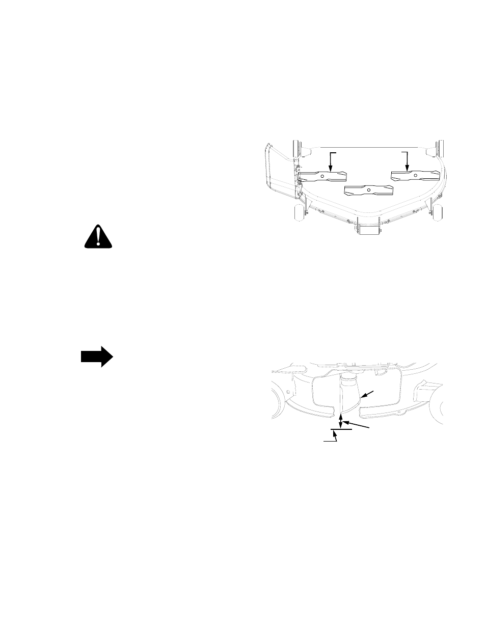
Carefully rotate the outer cutting blades so that
they are positioned perpendicular to the tractor
frame (See Figure 27).
Figure 27
5.
Referring to Figure 28, measure and record the
distance from the hard, level surface to the outer-
most cutting edge of the right blade. Repeat this
step for the left blade. If the two blade heights are
not within 1/16 inch, proceed to steps 6, 7 and 8. If
the two blade heights are within 1/16 inch, proceed
to FRONT TO BACK LEVELING ADJUSTMENT.
Figure 28
6.
Lower the deck onto the hard, level surface.
OUTER BLADES
TO FRAME
PERPENDICULAR
BLADE
MEASURE
HARD LEVEL
SURFACE
THIS DISTANCE