Warning – Cub Cadet 190-295-100 User Manual
Page 13
13
B. FRONT TO BACK LEVELING
The front lift rod must be correctly adjusted to maintain
the proper pitch of the deck when mowing uneven terrain.
1.
Adjust the front caster wheel arms and rear deck
rollers to their highest setting (lowest deck setting).
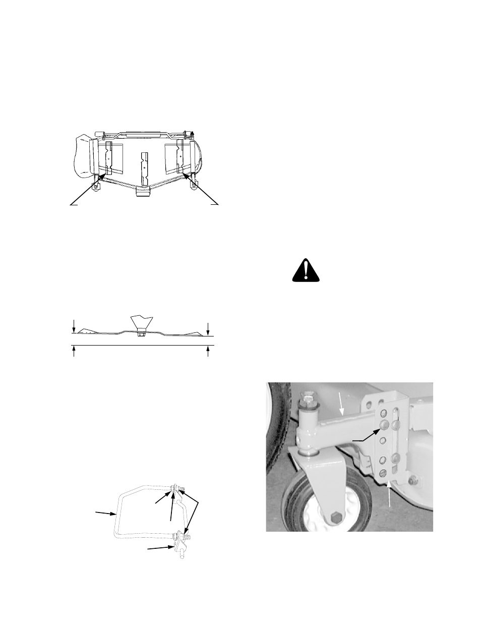
2.
Position the mower blades so the ends of each
blade point to the front and the rear of the tractor
(See Figure 21).
Figure 21
3.
Refer to Figure 22. Measure and record the dis-
tance from the front cutting edge to the ground
(measure A), and from the rear cutting edge to
the ground (measure B), for both outer blades.
The front edge of each blade (measure A) should
be lower than its back edge (measure B) by ap-
proximately 1/8 inch.
Figure 22
4.
Adjust the front lift rod as follows to attain the
proper pitch of the mower deck (See Figure 23).
• Loosen the hex jam nuts and lock washers on the
front lift rod.
• From the front of the tractor, turn the front hex lock
nuts clockwise to raise the front of the deck, or
counterclockwise to lower the front of the deck.
• Recheck the measurements described in step 3
and readjust the hex lock nuts until the proper
measurements are obtained.
Figure 23
NOTE: The front lift rod should be fully to the front of
both slots in the deck front roller bracket. If one side of
the rod does not contact the front of the slot, tighten the
corresponding lock nut as needed.
5.
Tighten the rear jam nuts and lock washers
against the backside of the front lift bracket after
adjustment of the rod has been completed.
C. SETTING THE CUTTING HEIGHT
NOTE: Cutting height adjustment should be performed
only AFTER the mower deck has been properly leveled.
If the mower deck is installed on a tractor without the
deck downstop feature, the cutting height is set by po-
sitioning the front caster wheel arms in one of five set-
tings in the height adjustment bracket of the deck.
If the deck is installed on a tractor with the downstop
feature, cutting height is set by using either the height
adjustment knob to set the deck downstop position or
by positioning the caster wheels in one of five settings.
Using the Caster Wheels and Rollers to Set
Cutting Height
WARNING
Before adjusting the caster wheel/roller posi-
tions, place the PTO switch in the “OFF” posi-
tion, engage the parking brake lever, and turn
the ignition key to the “OFF” position.
IMPORTANT: The index holes of the height adjust-
ment bracket are not sequential top to bottom in rela-
tion to their corresponding height setting. The lower
hole in the caster arm is used for settings 2 and 4 (See
Figure 24).
Figure 24
BLADES POINTING FRONT AND REAR
A
B
FRONT
CUTTING
EDGE
REAR
CUTTING
EDGE
FRONT
LIFT ROD
FRONT LIFT
BRACKET
HEX JAM NUT
LOCK WASHER
HEX
LOCK
NUTS
1
2
3
4
5
CASTER WHEEL ARM
HGT. ADJ.
BRACKET
INDEX HOLE POSITION 1 = LOWEST DECK SETTING
INDEX HOLE POSITION 5 = HIGHEST DECK SETTING
ADJUSTMENT
CLEVIS PIN