Alarm – COP-USA PKG-DVR04 User Manual
Page 9
9
32 路机型
Item
Item
Item
Item
Interface
Interface
Interface
Interface
Description
Description
Description
Description
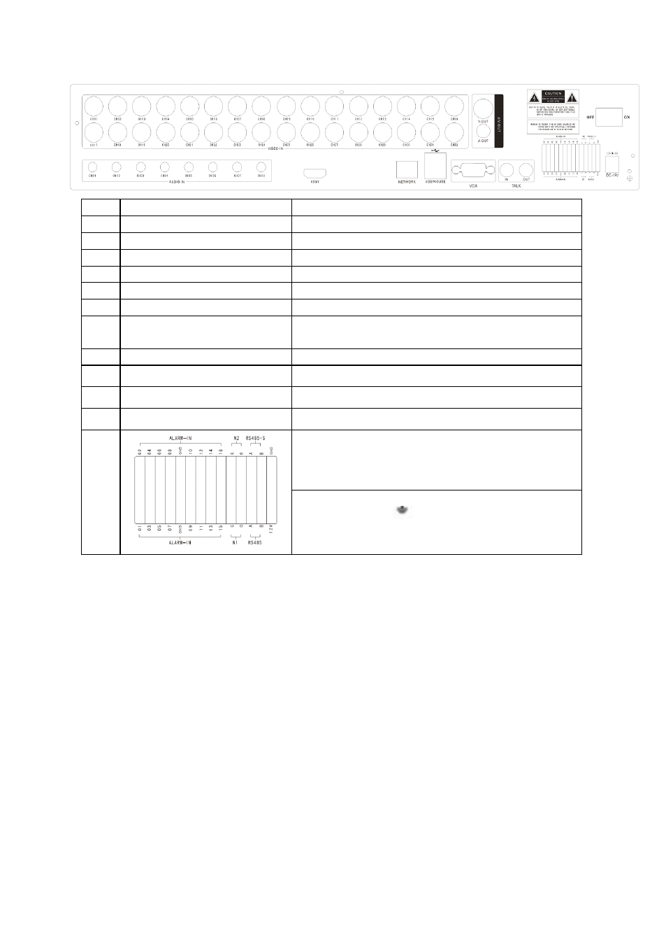
1
VIDEO IN
24ch video input
2
AUDIO IN
8ch audio input
3
V-OUT
1ch video output
4
A-OUT
1ch audio output
5
VGA
VGA monitor
6
NETWORK
RJ45 for internet
7
USB/ MOUSE
First USB for backup or upgrade system of DVR;Second
USB for mouse
8
ON/OFF
Power supply switcher
9
DC-12V
Power adaptor port
10
HDMI
HDMI interface
11
TALK
AUDIO TALKBACK
12
ALARM IN:16CH
alarm input port
RS-485:A, B
RS485-S A,B
ALARM OUT: N1 N2 for alarm output port, every channel
connect
C and O;
port is for GND;
2.1.3
2.1.3
2.1.3
2.1.3 Alarm
Alarm
Alarm
Alarm input
input
input
input port
port
port
port
8chanel alarm input, the mode of alarm input is no restriction (possible is normal open also normal close);
the GND alarm detector connect to COM under parallel connection (the power of alarm detector supply by
external power supply;
the ground terminal of alarm detector join-up in parallel with DVR;
the NC of alarm detector connect with the input end (alarm) of DVR;
when you want to reset the remote alarm of triggered , the +12V power supply of alarm detector supply by DVR,
for example, smoke detector.
When you select the external power supply, please share the GND with DVR;
Alarm
Alarm
Alarm
Alarm input
input
input
input circuit:
circuit:
circuit:
circuit: