COP-USA AS75W User Manual
Page 6
3
ON
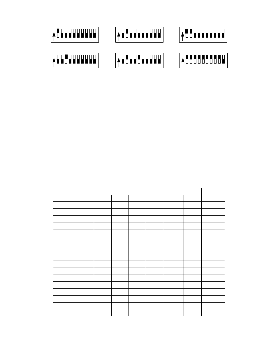
1 2 3 4 5 6 7 8 9 10
ON
1 2 3 4 5 6 7 8 9 10
ON
1 2 3 4 5 6 7 8 9 10
ON
1 2 3 4 5 6 7 8 9 10
ON
1 2 3 4 5 6 7 8 9 10
ON
1 2 3 4 5 6 7 8 9 10
P/ T Addr ess=1
P/ T Addr ess=2
P/ T Addr ess=3
P/ T Addr ess=4
P/ T Addr ess=5
P/ T Addr ess=511
2
、
Selection of the Terminal Resistor
As shown in Figure 1, DIP10 of the ID-CODE is the select switch of the 120
Ω
terminal resistor on the bus RS485, on which only one terminal resistor of the dome
camera at the farthest end can be connected, while the terminal resistors of other
devices should be opened.
3
、
Setup of the Protocol and the Default Baud Rate
As shown in Figure 1, SW2 is used to set the protocol of communication and the
baud rate used by the dome camera. DIP-4 to DIP-1 of SW2 is used to select protocols
and 16 different protocols can be selected in maximum. Following table shows states
of coding switches of protocols selected by the dome camera in which
●
means the
protocol has been integrated while
○
means the protocol is temporarily vacant.
Type of Protocols
Selection of Protocols
Normal Baud Rate Integrated
Protocol
DIP1 DIP2 DIP3 DIP4 DIP5 DIP6
SAMSUNG ON
OFF
OFF
OFF
OFF
ON
●
NEON ON
OFF
OFF
OFF
OFF
ON
●
Reserved OFF
ON
OFF
OFF
OFF
ON
○
PELCO-D ON
ON
OFF
OFF
OFF
OFF
●
PELCO-P/4800
OFF OFF ON OFF
ON OFF
●
PELCO-P/9600 OFF
ON
PANASONIC ON
OFF
ON
OFF
OFF
ON
○
Longcomity OFF
ON
ON
OFF
OFF
ON
●
HUNDA600 ON
ON
ON
OFF
OFF
ON
●
LILIN OFF
OFF
OFF
ON
ON
OFF
○
VICON ON
OFF
OFF
ON
ON
OFF
○
MOLYNX OFF
ON
OFF
ON
OFF
ON
○
KALATEL ON
ON
OFF
ON
ON
OFF
○
VCL OFF
OFF
ON
ON
OFF
ON
○
DAIWA ON
OFF
ON
ON
OFF
ON
●
ALEC OFF
ON
ON
ON
OFF
ON
●
Ultrak ON
ON
ON
ON
OFF
ON
●
Table 2
Some protocols and the states of the coding switches of normal baud rate of these