Setup of the dome camera – COP-USA CD54W-35Y User Manual
Page 4
Operation Manual for Intelligent Speed Dome Camera
3
27x
f =3.6 to 98 mm (F1.5 to F3.8)
1 Lux (Common / 0.01 Lux
(B & W)
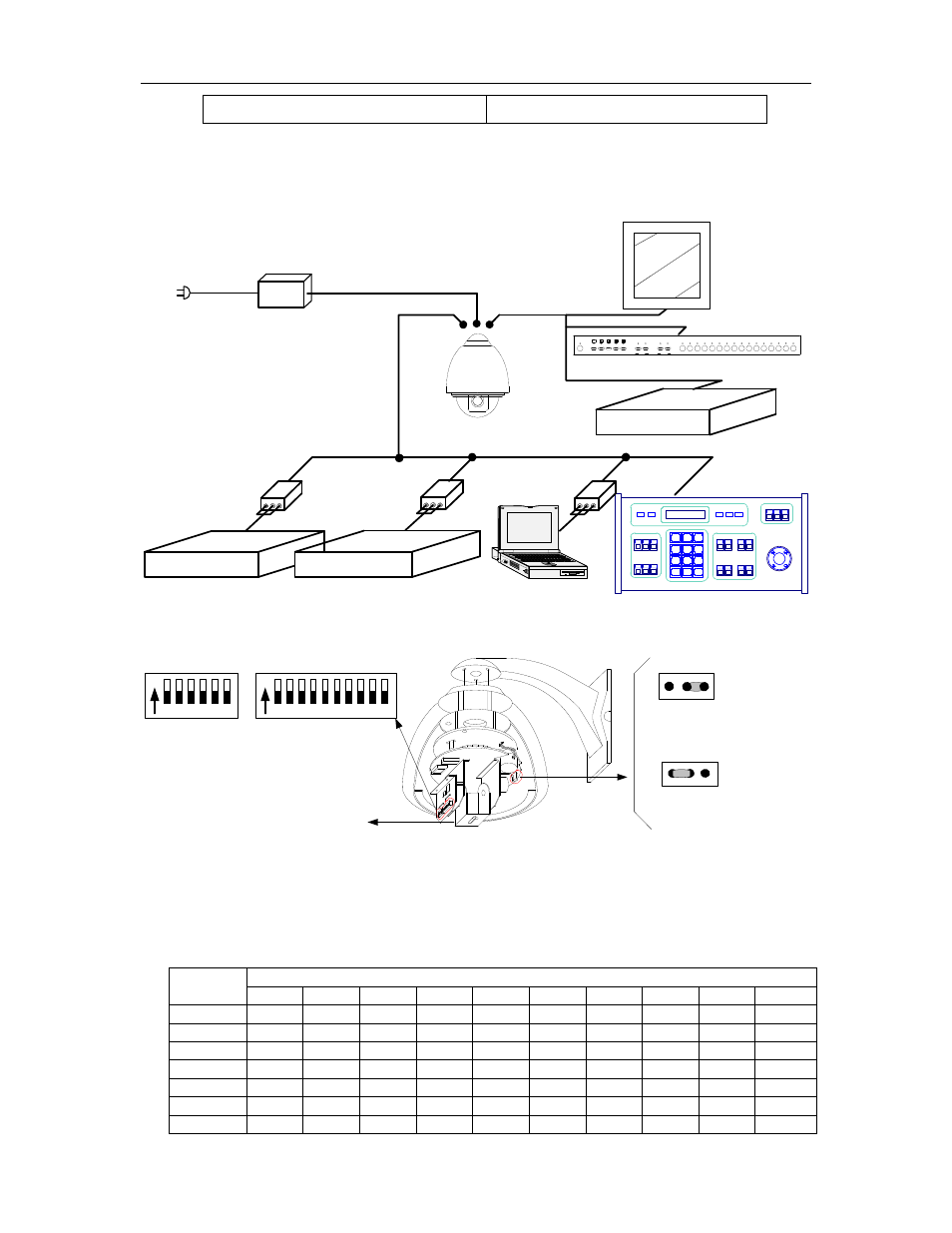
Ⅲ . Setup of the Dome Camera
1. Connection of the System
1) The Systematic Drawing of the Dome Camera
Power Adapt er
AC24V OUT
AD Mat r i x
B S W
RS232
B S W
Phi l i ps Mat r i x
Pr ot ocol Adapt er
Pr ot ocol Adapt er
Code Conver t er
RS- 485
RS- 485
RS- 485
RS- 485
Mat r i x
Mul t i pl exer
RS
-485
Power I N
VI DEO OUT
C
V
Moni t or
Dome Camer a
Power I N
Figure 1
2) Address / Protocol Coding Switch Drawing
ON
1 2 3 4 5 6
SW2
ON
1 2 3 4 5 6 7 8 9 10
SW1
Pr ot ocol Set
Addr ess Set
Br acket f or f i xed camer a
SW2: DI P1- - DI P4 Sel ect Pr ot ocol
SW2: DI P5- - DI P6 Sel ect Baud Rat e
JP
3
1 2
3
1 2
JP
120Ω terminal resistor is
opened for RS485 bus
120Ω terminal resistor is
connected on RS485 Bus
Figure 2
2. Setup of Coding Switch of Dome Camera. As shown in Figure 2, SW1 is used to set
address of the dome camera from 1 – 1023. The ID-CODE from DIP-10 to DIP-1 are
equivalent to a 10-bit binary digit. DIP-10 is MSB while DIP-1 is LSB. The state “ON” of
each bit means 1 while “OFF” means 0. Following table shows states of coding switches
of some addresses.
Dome
Address
ID-CODE Status
DIP-1 DIP-2 DIP-3 DIP-4 DIP-5 DIP-6 DIP-7 DIP-8 DIP-9 DIP-10
1
ON OFF OFF OFF OFF OFF OFF OFF OFF OFF
2 OFF
ON
OFF
OFF
OFF
OFF OFF OFF OFF OFF
3 ON
ON
OFF
OFF
OFF
OFF OFF OFF OFF OFF
4 OFF
OFF
ON
OFF
OFF
OFF OFF OFF OFF OFF
5 ON
OFF
ON
OFF
OFF
OFF OFF OFF OFF OFF
6 OFF
ON
ON
OFF
OFF
OFF OFF OFF OFF OFF
7 ON
ON
ON
OFF
OFF
OFF OFF OFF OFF OFF