Assembly – Cannon Instrument CT-600 (Contant Temperature Bath) User Manual
Page 8
6
CANNON
CANNON
CANNON
CANNON
CANNON
®
CT-500/600 Series II CONSTANT TEMPERATURE BATH
Version 3..2—March, 2007;
CANNON
CANNON
CANNON
CANNON
CANNON
®
Instrument Company
2139 High Tech Road • State College, PA • 16803 • USA
Assembly
Instrument placement
1. Place the bath control housing in the space that it will occupy when
the bath is operable. This should be a sturdy, level tabletop or bench
with a non-flammable surface.
CAUTION
Be careful when lifting the control housing; it is quite heavy.
Minimum clearance
The CT-500 series II bath requires 25 cm (10") of clearance to the
rear and sides of the unit.
Support/insulation
2. The CT-600 will require
two felt pads. The CT-500
will require one felt pad.
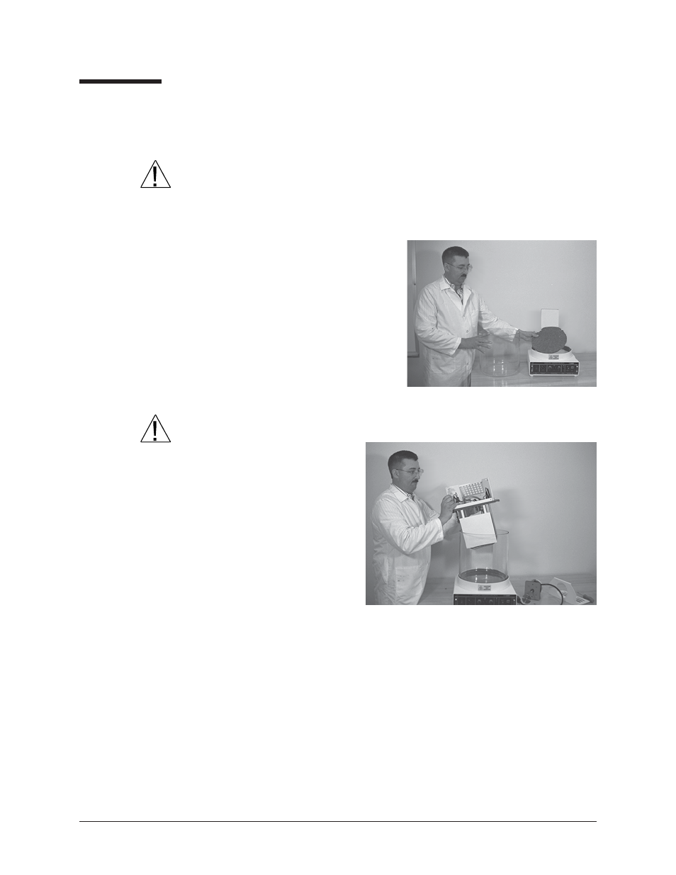
Felt pad placement
3. Place the felt pad(s) on top
of the insulating disk (see
Figure 3).
Bath jar placement
4. Place the glass bath jar on
top of the felt pad(s).
CAUTION
Be careful when lifting
the bath jar; it is quite
heavy.
5. Position the rear
cover containing
the motor housing,
heaters, cooling
coil, and baffle on
top of the jar (see
Figure 4), feeding
all connecting
cables from the
heaters, float
switch and control/overtemp probes through the vertical wiring
channel in the rear of the housing. The back of the motor housing
should fit over the vertical channel, and the groove on the underside
of the half-round cover should fit over the edge of the jar.
6. Place the front bath cover (with holes for the viscometers) on top of
the front half of the jar.
6b. CT-600 ONLY: Check for alignment of the the tab slots in the rear
housing with the screw holes in the vertical channel. If the alignment
is not correct, adjust the height of the bath vessel per steps 6c-6g.
Figure 3: Placing the felt pad(s)
on the insulating disk
Figure 4: Positioning the rear cover