Adaptive Technologies LTMB24 - 1x4 User Manual
Ltmb24-x4-rk
© 2008 ATM FLY-WARE Signal Hill, CA 90755 USA (562) 424-1100
030310-REV0
LTMB24-X4-RK
Installation Instructions
LT MB24 4 Wide Rigging Kit Grid
Thank you for choosing the LTMB24-X4-RK
Grid. This grid suspends 4 BOSE LT MB24-III
speakers in 4 sequential arrangements.
Important: Rigging overhead system requires
professional experience. Improperly installed
equipment can result in property damage,
personal injury, death and/or liability to the
installing contractor. Do not suspend if in
doubt about the integrity of the structure.
Caution: Due to the wide variety of structures,
environments, materials and rigging methods,
the installing contractor should exercise good
judgment in selecting the proper mounting area
and hardware.
Follow these instructions for the most
efficient and safest rigging results. .Do not
exceed the working load limit of
1200 lbs/545 Kg.
Package Contents:
1 pcs. LTMB24-X4-RK GRID
1 pc.
Instruction sheet, 8.5X11
16 pcs Hex Cap, 3/8-16x1.5,G8, blk
16 pcs. Split washer, 3/8, G8, blk
16 pcs. Flat washer, 3/8”, SAE
Step 1:
Check to make sure the holes of the grid matches the
holes on top and bottom of the speaker. Remove and
discard speaker screws where the grid will be attached
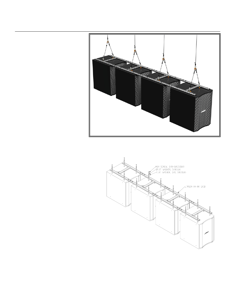
Step 2:
Set three speakers on the clean or padded floor with
the front facing the same direction. Lay the grid over
the top of the speakers and match the holes to the
holes on the speaker. Attach grid to speakers using the
supplied 3/8 hex bolt, washer and split washers.
Tighten bolts permanently (Figure 1).
Step 3:
Attach load rated suspension cables to the suspension
bracket on the four corners of the grid using load rated
hardware such as shackles (Figure 2). One can use
eight cable suspension points or eight points bridled to
a four point suspension (Figure 2).
Step 4:
Check all connections before suspending the speaker cluster.
Figure 1