Chapter two – the rear panel, Electrical power, Audio connections – 360 Systems Instant Replay DR-554 User Manual
Page 27: Caution, Warning, Power switch, Fuses, Audio inputs, The p, Is located next to the ac p
Instant Replay Owner's Manual
Page 27
CHAPTER TWO – The Rear Panel
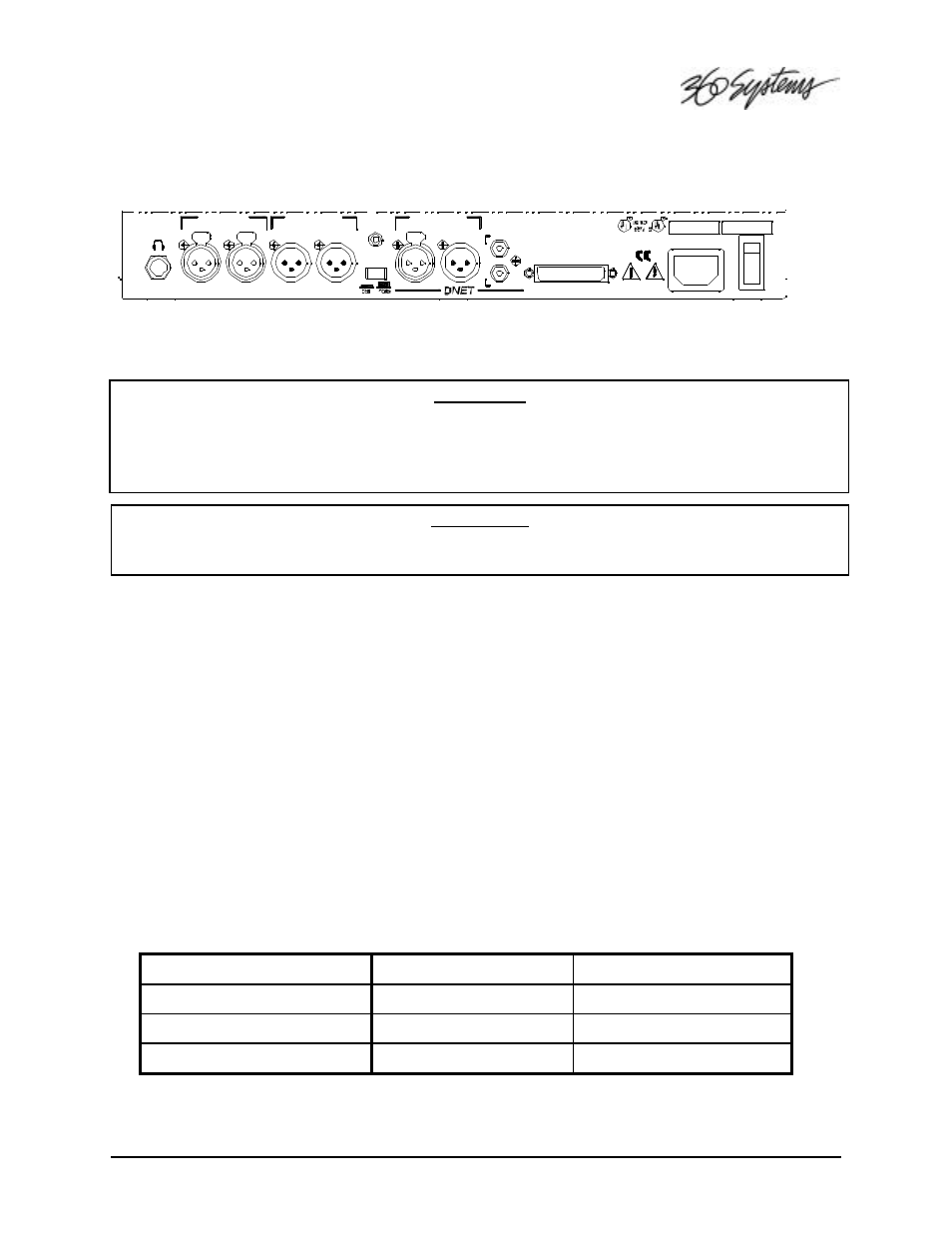
INSTANT REPLAY REAR PANEL
ELECTRICAL POWER
CAUTION!
CONNECT THIS PRODUCT ONLY TO AN AC POWER SOURCE WITHIN THE VOLTAGE AND
FREQUENCY RANGE INDICATED ON THE REAR PANEL. THE PRODUCT IS SUPPLIED WITH A
DETACHABLE IEC TYPE AC LINE CORD APPROPRIATE TO THE COUNTRY TO WHICH THE UNIT
WAS ORIGINALLY DELIVERED. CHECK TO SEE THAT IT MATCHES THE ELECTRICAL OUTLET
YOU WILL BE USING.
WARNING:
REPLACE POWER CORD ONLY WITH UNDERWRITERS LABORATORIES (UL) LISTED CORD OF
EQUIVALENT TYPE AND RATING!
Power Switch
The P
OWER
S
WITCH
is located next to the AC P
OWER
I
NPUT
on the rear of the product.
Fuses
The fuses in this product are not user replaceable. Failure of a fuse is an indication of other
component failure, and will require service by a qualified repair technician. Contact 360 Systems, or
your 360 Systems distributor.
AUDIO CONNECTIONS
Audio Inputs
The A
NALOG
I
NPUTS
are a pair of female XLR-3 connectors marked L
EFT
and R
IGHT
. The inputs are
electronically balanced, with an impedance of 40k ohms. With the I
NPUT
L
EVEL
controls up full, a
6.75dBu tone will produce a full scale output, approximately 15dBu with the O
UTPUT
A
TTENUATOR
in the –10 position and 25 dBu in the 0 position.
Input cables should be wired as follows:
XLR Connector Pin
Balanced Connection
Unbalanced Connection
PIN 1
COMMON
GROUND
PIN 2
+ INPUT
SIGNAL
PIN 3
- INPUT
No Connect
T
ABLE OF
I
NPUT AND
O
UTPUT
C
ONNECTIONS
ITE EQUIPMENT
ATTEN
AES 75 OHM
360 SYSTEMS, WESTLAKE VILLAGE, CALIFORNIA, USA
MADE IN USA
OUT
GPI/PLAY
OUTPUT
RIGHT
LEFT
ANALOG INPUT
ANALOG OUTPUT
LEFT
RIGHT
IEC-958 II
AES/EBU DIGITAL
IN
OUT
EXPANSION
PRINTER
IN
O
SERIAL #
115-230VAC, 50-60Hz
MODEL #
1.2A MAX
I