Som 9s, 6 system layouts, R1 s2 s1 – STIEBEL ELTRON SOM 9s User Manual
Page 9
© Stiebel 11091_SOM_9s.mon
us.ind
d
9 |
SOM 9s
2.6
System layouts
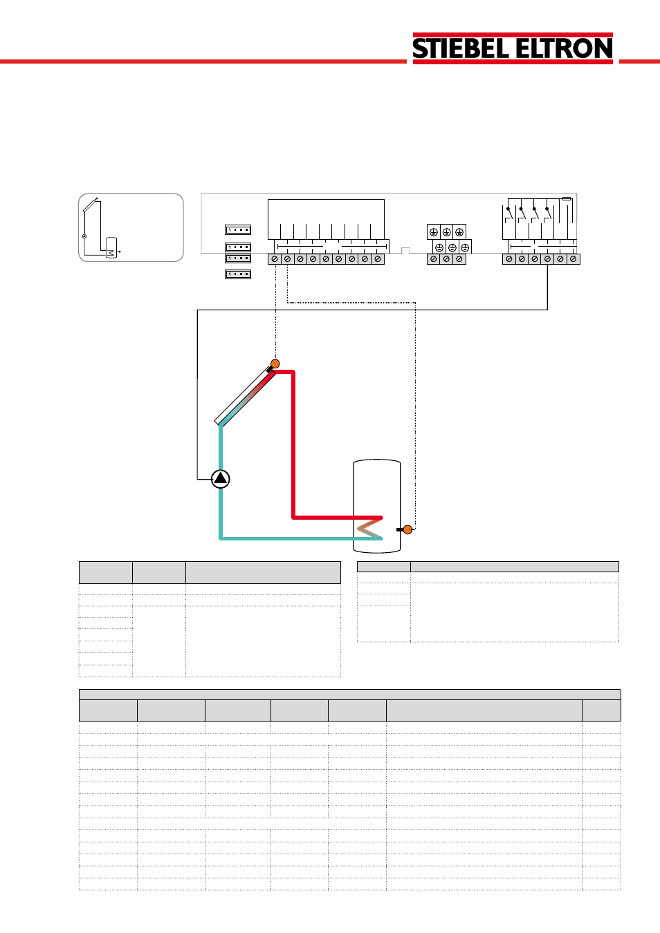
System 1
Standard solar system with 1 tank
The controller calculates the temperature difference bet-
ween collector sensor S1 and tank sensor S2. If the diffe-
rence is larger than or identical to the adjusted switch-on
Relay
Description
R1
Solar pump
R2
optional:
Thermal disinfection
Booster pump
Parallel relay
Heat dump
R3
R4
Adjustment channels
Channel
Sub channel 1
Sub channel 2 Factory
setting
Change to
Description
Page
ARR
1
System
78
LOAD >
Loading
DT O
12 °R
Switch-on temperature difference
78
DT F
8 °R
Switch-off temperature difference
78
DT S
20 °R
Set temperature difference
78
RIS
4 °R
Rise
78
S MAX
140 °F
Tank maximum limitation
78
SMAXS
2
Sensor tank max
79
COL >
Collector
CEM
270 °F
Collector emergency temperature
80
OCCO**
OFF
Option collector cooling
80
CMAX
230 °F
Maximum collector temperature
80
OCMI
OFF
Option collector minimum limitation
80
CMIN
50 °F
Minimum collector temperature
80
Sensor/Ter-
minal
Designation Description
S1
TCOL
Temperature collector
S2
TSTB
Temperature tank bottom
S3
Optional sensor for measurement
purposes or options
S4
S5
VFS
RPS
V40
temperature difference, the pump (R1) will be switched on
and the tank will be loaded until the switch-off temperature
difference or the maximum tank temperature is reached.
R1
S2
S1
Temp. Sensor
Pt1000
L
R3
R2
R1
GND
S1
S2
S3
S4
S5
VBus
PWM
1
PWM
2
N
R4
V40
L'
VFS
RPS
out
in