Som 9s – STIEBEL ELTRON SOM 9s User Manual
Page 29
© Stiebel 11091_SOM_9s.mon
us.ind
d
29 |
SOM 9s
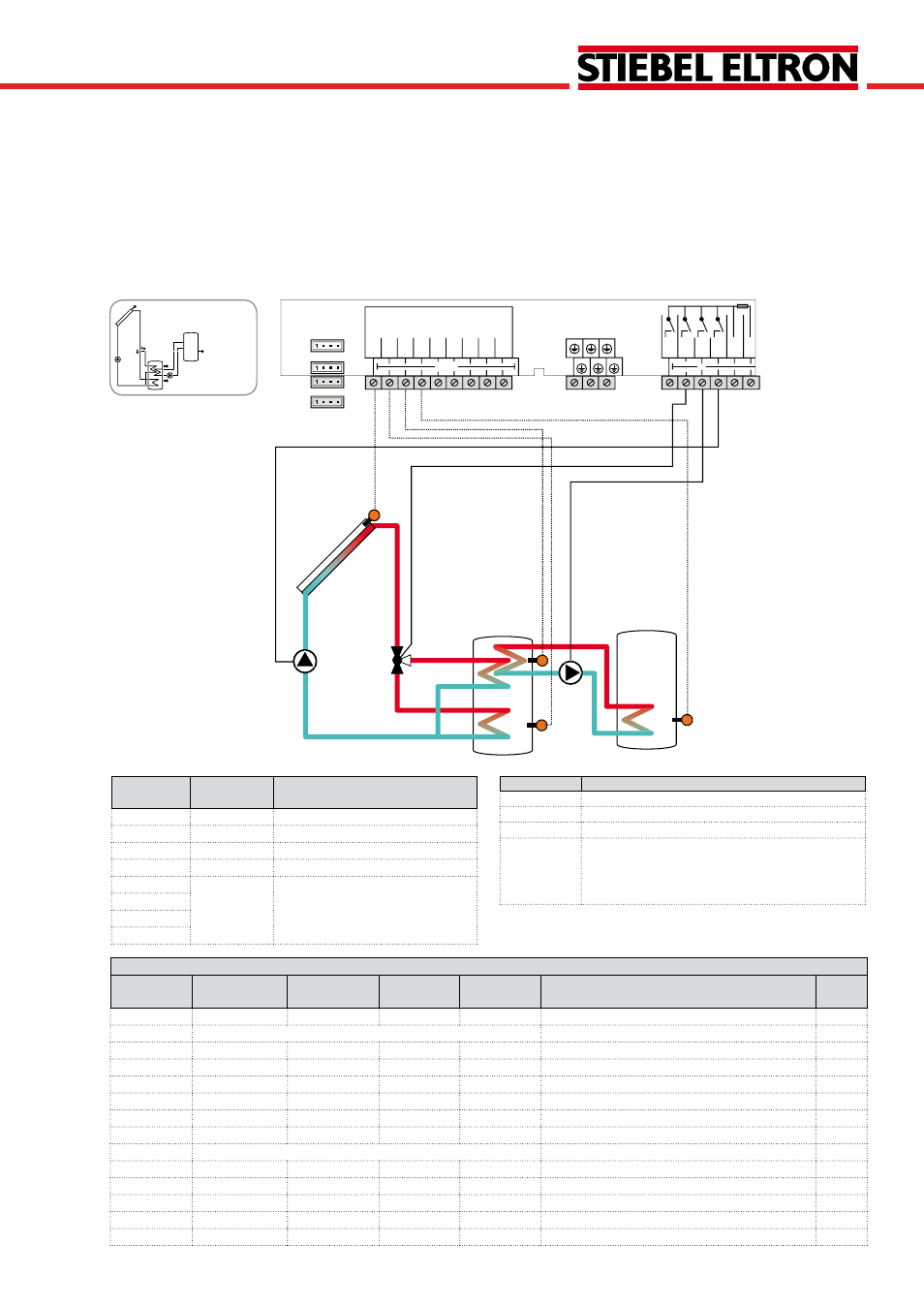
The controller compares the temperature at sensor S1 to
the temperatures at sensors S2 and S3. If the measured
temperature differences are higher than the adjusted switch-
on temperature differences, the pump (R1) will be activated
and the corresponding tank zone will be loaded up to the
adjusted maximum temperature via the valve (R3).
The priority logic effects prior loading of the upper zone
of the tank.
Heat exchange control to an existent tank via an additional
pump (R2) can be carried out with another temperature
differential function (S3 heat source/S4 heat sink).
Sensor/Ter-
minal
Designation
Description
S1
TCOL
Temperature collector
S2
TST1B
Temperature tank 1 bottom
S3
TSTT
Temperature tank 1 top
S4
TST2B
Temperature tank 2 bottom
S5
Optional sensor for measurement
purposes or options
VFS
RPS
V40
Relay
Description
R1
Solar pump
R2
Heat exchange pump
R3
3-port valve tank top/bottom
R4
optional:
Thermal disinfection
Parallel relay
Heat dump
System 11
Solar system with vertical tank loading and heat exchange control
Adjustment channels
Channel
Sub channel 1
Sub channel 2 Factory
setting
Change to
Description
Page
ARR
1
11
System
78
LOAD1 >
Loading 1
DT1O
12 °R
Switch-on temperature difference 1
78
DT1F
8 °R
Switch-off temperature difference 1
78
DT1S
20 °R
Set temperature difference 1
78
RIS1
4 °R
Rise 1
78
S1MAX
140 °F
Tank maximum limitation 1
78
SMXS1
2
Sensor tank max 1
79
LOAD2 >
Loading 2
DT2O
12 °R
Switch-on temperature difference 2
78
DT2F
8 °R
Switch-off temperature difference 2
78
DT2S
20 °R
Set temperature difference 2
78
RIS2
4 °R
Rise 2
78
S2MAX
140 °F
Tank maximum limitation 2
78
R2
R3
S3
R1
S4
S2
S1
Temp. Sensor
Pt1000
L
R3
R2
R1
GND
S1
S2
S3
S4
S5
VBus
PW
M
1
PW
M
2
N
R4
V4
0
L'
VFS
RPS
out
in
Note: 3-port valve normally open - tank bottom