General operation, Features – Steffes Mini Receiver User Manual
Page 3
NOTES
(For reference to these notes, refer to the wiring diagrams on
Pages 6 and 7 in this manual.)
NOTE 1: For more information on the dip switches, refer to the Dip Switch
Settings section in this manual.
NOTE 2: Mini receiver configuration must be specified at the time of factory
order.
NOTE 3: The mini receiver operates on 120V or 208V/240V, single phase. In the
single and double pole configuration mini receivers, line voltage
connections must be made in the terminal block to configure it to the
voltage input being connected to. The six pole configuration mini
receiver is factory configured to operate on 208V/240V. If connecting it
to 120V, the line voltage connections in the terminal block must be
reconfigured and L1 must be the ungrounded leg.
NOTE 4: All line voltage wiring in this device must remain below and in front of
the line voltage barrier inside the mini receiver enclosure.
NOTE 5: In the 6-pole mini receiver, circuit 1 feeds both output circuit 1 and the
mini receiver’ s internal controls.
NOTE 6: With the 6-pole mini receiver, loads connected between L1 & L2 on
circuit 1 will be uninterrupted. Loads connected between T1 & L2 on
circuit 1 will be interrupted.
NOTE 7: Circuit 1 maximum fuse size is 20 amps. Maximum load is 16 amps.
Any loads requiring greater than a 20 amp circuit MUST never be
connected to circuit 1.
NOTE 8: Circuits 2-6 maximum fuse is 30 amps. Maximum load is 24 amps.
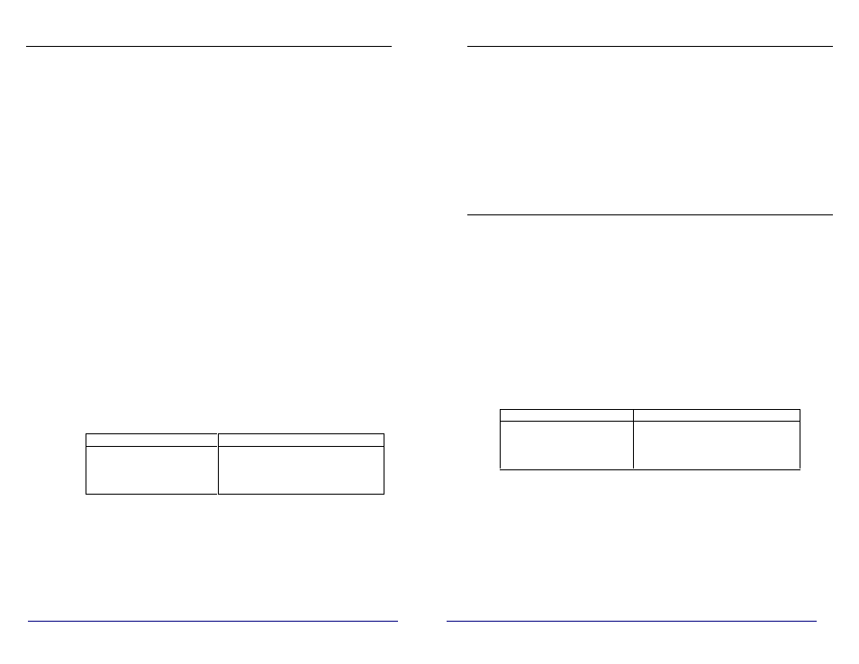
Maximum Fuse Size (6-pole) Total Input Circuit Ampacity (6-pole)
Circuit 1 = 20 AMP
(16 AMP Load, Max)
Surface Mounted = 120 AMPS
Flush Mounted = 80 AMPS
Circuit 2-6 = 30 AMP
(24 AMP Load, Max)
NOTE 9: To ensure proper communications between the PLC Mini Receiver and
it’ s correlating transmitter, the mini receiver MUST be grounded. The
system grounding and bonding must be sized and installed in
compliance with all applicable codes.
GENERAL OPERATION
The Steffes Power Line Carrier (PLC) Mini Receiver is designed to provide
wireless control of one electrical circuit (single pole configuration), two electrical
circuits (double pole configuration), or six electrical circuits (six pole
configuration). It receives signals through the existing power lines from the
Steffes Power Line Carrier (PLC) Transmitter or Comfort Control Relay Panel
(CCRP). The built-in 30 AMP relay(s) are capable of controlling devices such as:
ETS heaters, water heaters, baseboards, electric furnaces, dryers, dishwashers, hot
tubs, ceiling cables, or other electrical equipment. When the mini receiver receives
a signal, its relay(s) are activated to control the device(s) connected to them. This
type of control can minimize the overall cost of controlling electrical devices.
FEATURES
w One, two, or six DC held, 30 AMP, board mounted relay(s) pre-wired with 10
AWG leads. (Configuration must be specified at the time of factory order.)
w Single and double pole configurations are UL and cUL safety listed.
w Receives peak and anticipated peak (pre-peak) control signals via the power
lines from the Steffes PLC transmitter system.
w Fifteen selectable communication channels.
w Capable of controlling a device on a rate/control strategy separate from the
master control.
w All configurations are available in metal, flush or surface, indoor mounted
enclosures with power company seal/lockout provision.
Single and Double Pole Configurations: 6” x 6” x 3” (Outdoor enclosure
available as special a factory order.)
Six Pole Configuration: 10” x 13” x 3”
Maximum Fuse Size (6-pole) Total Input Circuit Ampacity (6-pole)
Circuit 1 = 20 AMP
(16 AMP Load, Max)
Surface Mounted = 120 AMPS
Flush Mounted = 80 AMPS
Circuit 2-6 = 30 AMP
(24 AMP Load, Max)
w Controls 120V or 208V/240V, single phase devices connected to single or
three phase systems.
w Indicator lights to monitor PLC operation or relay status.
w Optional 90-minute peak override module available.
8
1