Two-mode figure 20 ~ c ~ c ~ c ~ c ~ c, Variable charge figure 22 multi-mode figure 21 – Steffes 612EXT Owner & Installers Manual User Manual
Page 19
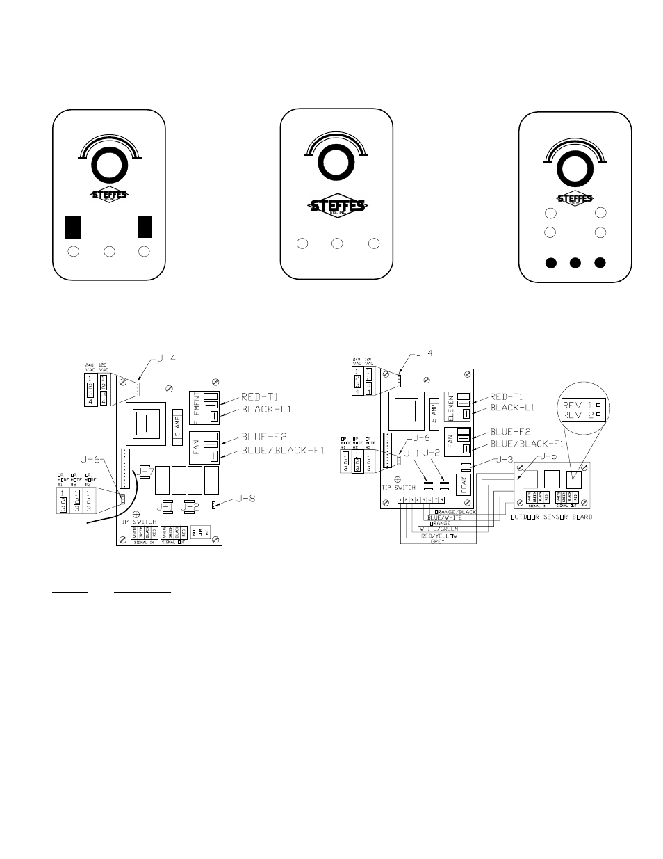
Jumper Configurations
Jumper
Connections
J-1
Connected with a jumper in all modes except when using automatic charge control with two-mode circuit boards.
J-2
Always connected with jumper.
J-3
Connected with violet jumper except when fans are to be disabled during the charge period.
J-4
Input voltage selector: When fan circuit input voltage is 208-240 VAC,
J4-2 to J4-3 are connected. When fan circuit input voltage is 120 VAC, J4-1 to J4-2 and J4-3 to J4-4 are connected.
J-5
Factory wired with plug-in header connector.
J-6
Fan run time based charging jumper: In OP. MODE #1, off-peak heat call can bring core to a 1/3 charge level when no
other charging method is being used. OP. MODE #2 will allow off-peak heat calls to bring core to full charge. OP. MODE
#3 will not allow core charging based on fan run time (positive off).
J-7
24 VDC output from circuit board used for auxiliary control devices or to run peak and pre-peak signals on DC power
rather than AC power.
J-8
When connected, enables fans during pre-peak charging mode.
CIRCUIT BOARD FACE PLATES - EXT SERIES
CHARGE CONTROL CIRCUIT BOARD CONFIGURATORS - EXT SERIES
Multi-Mode Circuit Board Configurator
FIGURE 23
Two-Mode Circuit Board Configurator
FIGURE 24
(NOTE:
When reading the Typical System Wiring Diagrams and Unit Wiring Diagrams, use
these skematics to determine which circuit board your heater incorporates.)
~ C
~ C
~ C
~ C
~ C
OMFOR
OMFOR
OMFOR
OMFOR
OMFORT
T
T
T
T
Z
Z
Z
Z
Z
O
O
O
O
ONE
NE
NE
NE
NE
~
~
~
~
~
85
85
85
85
85
55
55
55
55
55
O
O
O
O
O N
N
N
N
N
OFF
OFF
OFF
OFF
OFF
HIGH
HIGH
HIGH
HIGH
HIGH
M E D
M E D
M E D
M E D
M E D
LO
LO
LO
LO
LOW/A
W/A
W/A
W/A
W/AUTO
UTO
UTO
UTO
UTO
HEA
HEA
HEA
HEA
HEAT
T
T
T
T
STORA
STORA
STORA
STORA
STORAGE
GE
GE
GE
GE
CHARGE
CHARGE
CHARGE
CHARGE
CHARGE
LEVEL
LEVEL
LEVEL
LEVEL
LEVEL
OFF-PEAK
OFF-PEAK
OFF-PEAK
OFF-PEAK
OFF-PEAK
CHARGING
CHARGING
CHARGING
CHARGING
CHARGING
O
O
O
O
O N-PEAK
N-PEAK
N-PEAK
N-PEAK
N-PEAK
TWO-MODE
FIGURE 20
~ C
~ C
~ C
~ C
~ C
OMFOR
OMFOR
OMFOR
OMFOR
OMFORT
T
T
T
T
Z
Z
Z
Z
Z
O
O
O
O
ONE
NE
NE
NE
NE
~
~
~
~
~
Hi
Hi
Hi
Hi
High
gh
gh
gh
gh
Lo
Lo
Lo
Lo
Low
w
w
w
w
CHARGING
CHARGING
CHARGING
CHARGING
CHARGING
O
O
O
O
OVERRIDE
VERRIDE
VERRIDE
VERRIDE
VERRIDE
SENSOR
SENSOR
SENSOR
SENSOR
SENSOR
PEAK
PEAK
PEAK
PEAK
PEAK
O
O
O
O
ON-PEAK
N-PEAK
N-PEAK
N-PEAK
N-PEAK
OFF-PEAK
OFF-PEAK
OFF-PEAK
OFF-PEAK
OFF-PEAK
CANCEL
CANCEL
CANCEL
CANCEL
CANCEL
--O
--O
--O
--O
--O
VERRIDE
VERRIDE
VERRIDE
VERRIDE
VERRIDE
--
--
--
--
--
VARIABLE CHARGE
FIGURE 22
MULTI-MODE
FIGURE 21
O
O
O
O
O N-PEAK
N-PEAK
N-PEAK
N-PEAK
N-PEAK
CHARGING
CHARGING
CHARGING
CHARGING
CHARGING
~ C
~ C
~ C
~ C
~ C
OMFOR
OMFOR
OMFOR
OMFOR
OMFORT
T
T
T
T
Z
Z
Z
Z
Z
O
O
O
O
ONE
NE
NE
NE
NE
~
~
~
~
~
85
85
85
85
85
55
55
55
55
55
OFF-PEAK
OFF-PEAK
OFF-PEAK
OFF-PEAK
OFF-PEAK