Steffes 612EXT Owner & Installers Manual User Manual
Page 17
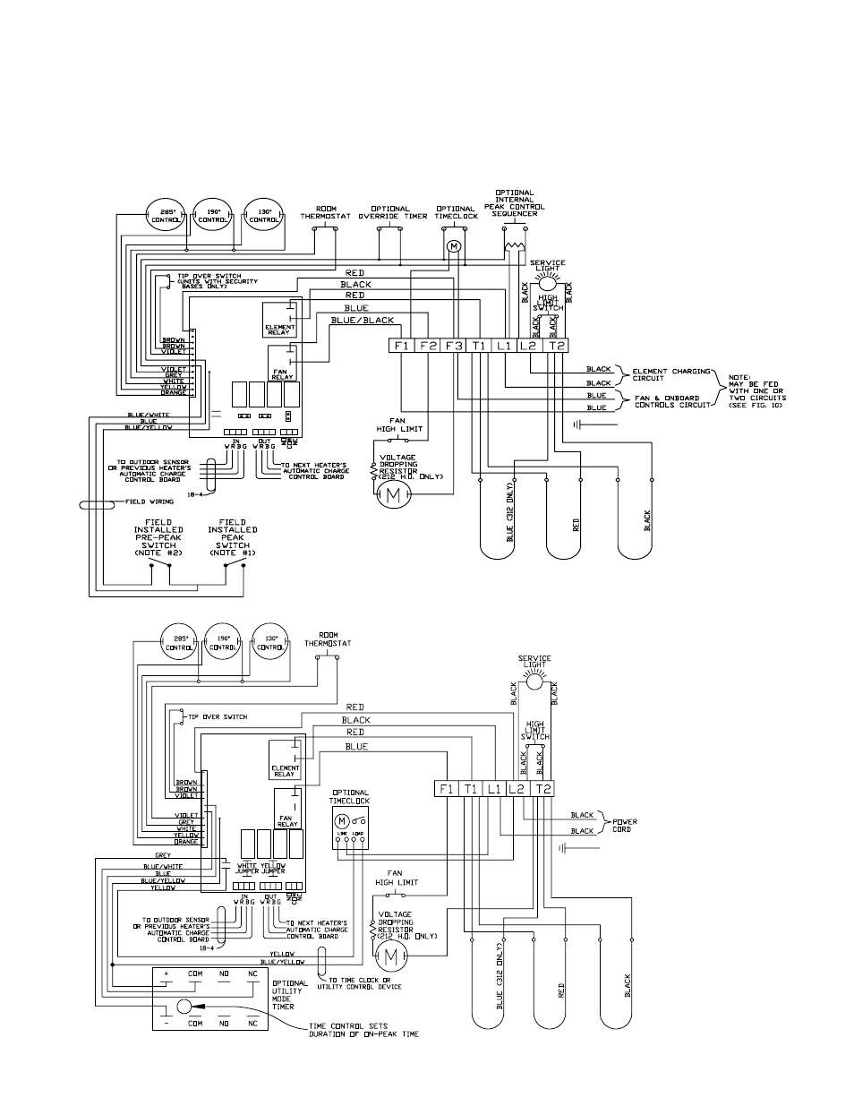
UNIT WIRING DIAGRAMS - EXT SERIES CONTINUED . . .
Connections shown are for 230 VAC fans.
See Unit Identification Label on lower right side panel of unit for proper fan and element voltages.
(Refer to the Face Plate Diagrams to determine which circuit board your heater incorporates.)
Models: 212EXT - 312EXT
(shown with multi-mode circuit board)
FIGURE 16
NOTES FOR FIGURE 16:
1. If peak switch is open, no charg-
ing can occur.
2. If the pre-peak switch is open,
the elements will charge to a
level based on outdoor tempera-
ture. If the pre-peak switch is
closed, the elements will charge
for the duration of heat calls
only.
Models: 212EXT - 312EXT
(shown with multi-mode circuit board
and 120 Volt cord connected)
FIGURE 17
This manual is related to the following products: